Sensor setup – Haltech E8 User Manual
Page 47
Haltech E11/E8 Instruction Manual
Sensor Setup
The Haltech Halwin software allows the user to calibrate sensor inputs to their own calibration, this is
useful when using a vehicles OEM sensors or when haltech sensors cannot be used for some other
reason.
Calibrating The Throttle
The throttle sensor must be calibrated so that the ECU knows the start and stop positions of the sensor.
Always calibrate the throttle even if a map is supplied as the throttle calibration can vary between even
identical models of cars.
Before you begin, ensure that the closed throttle position is in a position that you wish to leave it in. If you
change the closed throttle position, re-calibrate your throttle. Usually, the throttle is set to ensure a slow
idle when the throttle is closed. If the required opening for idle is not known, make an estimate but keep in
mind that this may be the reason for poor idle later on, and further adjustment may be needed. Choose
the "calibrate throttle" option from the options menu and follow the instructions on the screen.
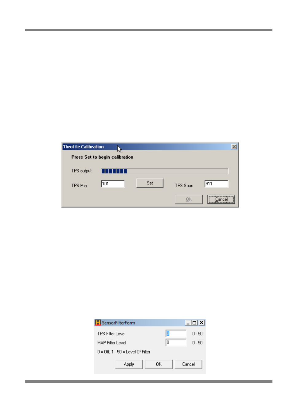
Figure 39 - Throttle Position Sensor Calibration
The calibration process begins by pressing the Set button as shown in Figure 39 above.
The dialog will ask you to set the minimum throttle opening. It is a good idea to give the throttle a quick
press to see if it returns to the same position consistently without sticking. After you are happy that the
throttle is returning consistently to the same zero position, press the Set button once more.
The dialog will then ask you to hold the throttle at full throttle. Whilst holding the throttle all the way down,
press the Set button again on the dialog.
If the calibration process was smooth, commit the new calibration to the ECU by pressing the OK button.
Sensor Filtering
Allows for the TPS and MAP sensor inputs to be filtered. This can help on applications where there is
severe noise in the electrical system causing the TPS or MAP sensor to become unstable. If this occurs
throttle pumps can be falsely triggered causing the engine to run poorly.
The lower the number in the filter level the less filtering that is applied, the higher the number the more
filtering applied.
Figure 40 - Sensor Input Filtering
Copyright © Haltech 2008
Page: 47