Fuel rail and pressure regulators, Ignition systems, Dumb ignitors – Haltech E8 User Manual
Page 151
Haltech E11/E8 Instruction Manual
maximum power. With the engine switched off (injectors closed) feed the return line of the fuel pressure
regulator to a measuring container. In the case of a turbo- or supercharged engine, pressurise the
manifold pressure port of the fuel pressure regulator to the maximum boost of the engine. This is
necessary as the flow rate of the pump decreases with output pressure. Power the pump for one minute
and calculate the hourly fuel flow rate of the pump.
Since the pressure regulator operates on a return system, there should always be fuel being returned to
the tank, even when fuel flow to the engine has reached its maximum. If this fails to happen, the fuel
pressure will fall out of regulation. Therefore the fuel pump must be capable of delivering significantly
more fuel than the engine is going to use. As a guide, the pump should flow 30% more fuel than
consumed by the engine.
If you cannot achieve the required fuel flow from one pump, you can employ two pumps in parallel. If you
choose to use a low-pressure pump to augment the fuel flow of a high-pressure pump, place a check
valve after the low-pressure pump.
Fuel Rail and Pressure Regulators
A long fuel rail with narrow internal diameter will suffer from pulsation in the fuel rail. The internal rail
diameter should be around 12mm (½"). Even so, oscillations may occur, particularly if the injectors are
large. A fuel damper can help in removing these oscillations. If running a multipoint set-up, batch fire
injection will also reduce oscillation amplitude. Oscillations may occur only within a certain rpm range, so a
fuel pressure meter should be monitored throughout the driving range of the engine.
On V configuration motors, it may be more practical to employ two regulators, one on each bank's rail.
The fuel from the pump can be split to the two rails, and the return line from the two regulators can be
joined. Since pressure regulators work within certain flow limits, this may also save having to purchase an
expensive high pressure / high flow regulator.
Ignition Systems
The ECU’s interface to the ignition system is through the Ignition Module (sometimes referred to as an
Ignitor or Spark Amplifier). There are two distinct types of Ignition Module available in common use on
factory ignition systems.
Dumb Ignitors
The Dumb Ignitors are found on nearly all engines that have an existing engine management system that
controls spark timing, they require the ECU to perform the dwell control or charge time of the ignition coils.
The signal from the ECU determines the charge time of the coil and tries to maintain a constant charge
time at all engine speed where possible.
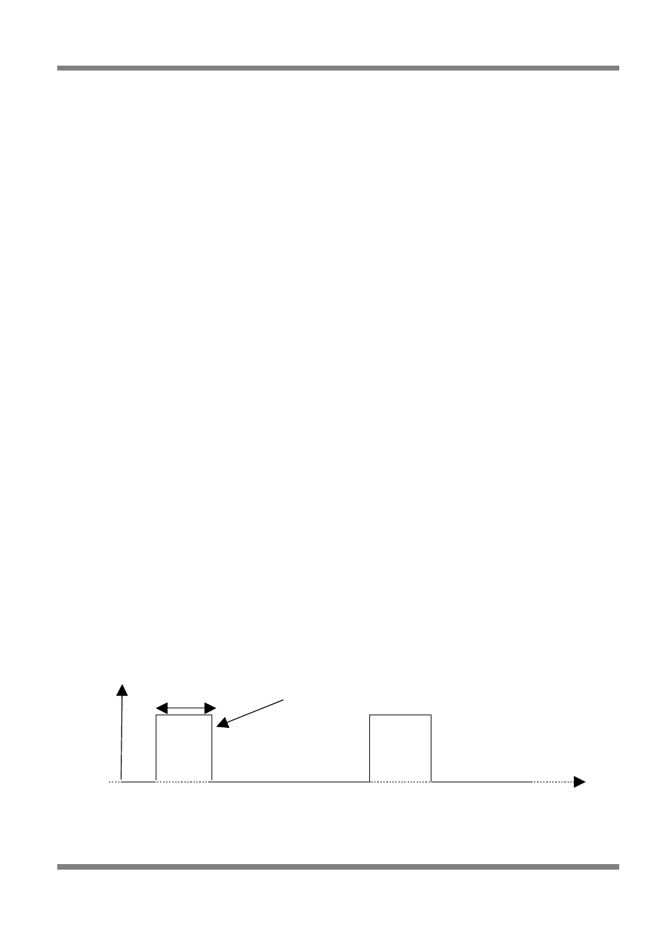
For a dumb ignitor with a falling edge spark edge, with 4ms of coil charge time, the ECU ignition output
waveform will look like the following waveform:
Copyright © Haltech 2008
Page: 151
GND
+12V
4ms Charge
time
Time
Voltage
Spark Edge