Sensors and device pin outs, Manifold absolute pressure sensor – Haltech E8 User Manual
Page 11
Haltech E11/E8 Instruction Manual
Sensors and Device Pin Outs
Manifold Absolute Pressure Sensor
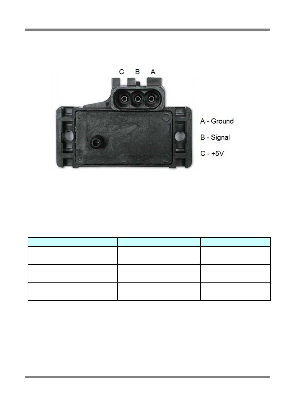
Figure 1 - MAP Sensor
The MAP sensor is used to convert the manifold pressure into an electrical signal for the ECU to use. The
sensor works in absolute pressures, thus its calibration is not affected by changes in barometric pressure.
The vacuum and, in the case of forced air induction engines, the pressure under boost, is proportional to
the load under which the engine is operating and the ECU uses the electrical signal as a load reference.
There are three types of MAP sensors that can be used with the system. Which sensor is required
depends on the engine set-up.
Sensor Name
Range of Operation
Application
1 Bar Sensor (Part No. 039 4070)
(Green plug)
-100kPa to 0 kPa
Normally Aspirated Engines
2 Bar Sensor (Part No. 886 3189)
(Orange plug)
-100kPa to 100kPa
(15 psi of boost, 1 atmosphere)
Turbo or Supercharged
Engines up to 100kPa boost
3 Bar Sensor (Part No. 749 3169)
(Orange plug)
-100kPa to 200kPa
(30 Psi of boost, 2 atmospheres)
Turbo or Supercharged
Engines up to 200kPa boost
Note:
Make sure you have the correct MAP sensor for your engine. The first three digits of the part
number are stamped on the sensor housing.
The MAP sensor is usually mounted high on the engine bay firewall or inner guard using two screws and
with the hose nipple facing outwards. Connect the sensor to the inlet manifold via a short length of
vacuum hose and fasten with either hose clamps or nylon cable ties. Connect the sensor to the main
wiring harness using the appropriate plug. Avoid mounting the sensor below the level of the fuel injectors,
because fuel may collect in the vacuum hose and run down into the sensor. The sensor assembly is
weatherproof but it is good practice to mount the sensor in a protected position away from moisture and
heat.
Copyright © Haltech 2008
Page: 11