Haltech E8 User Manual
Page 113
Haltech E11/E8 Instruction Manual
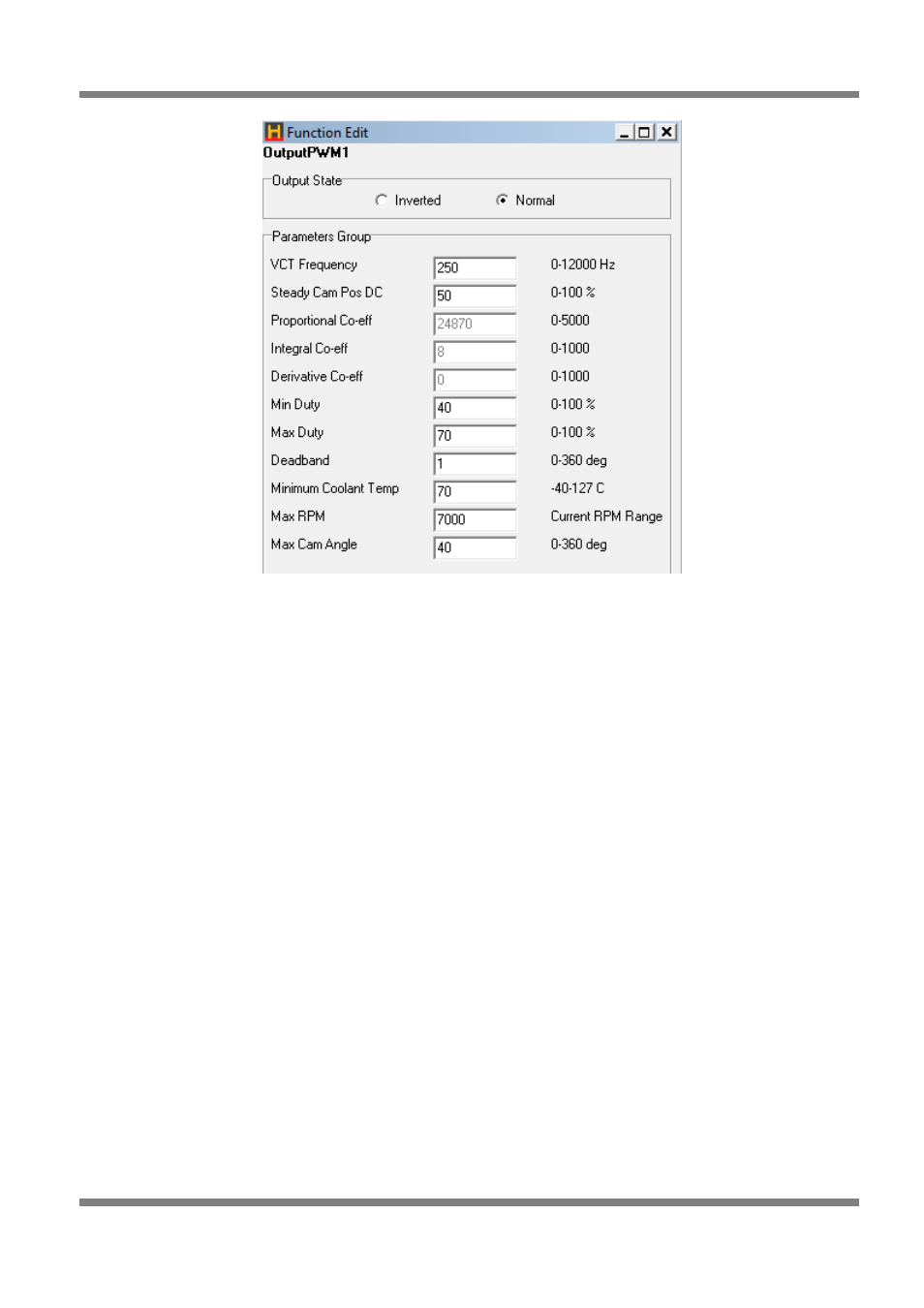
Figure 112 - Variable Cam Timing Control Parameters
Variable Cam Timing Control Setup
If the cam timing fluctuates or oscillates, reduce the PID parameters slowly until the oscillation stops. If the
cam timing is slow to reach the target, increase the PID parameters slowly until it begins to oscillate and
then reduce the values slightly. The derivative term will usually stay at zero.
1. Zero the VCT Cam Angle Map and make sure the engine is up to operating temperatures.
2. Enable the VCT Control Input and set up the values or use the default values as stated above.
Adjust the trigger angle value until the cam angle reads 0 degrees (Make sure that the VCT Control
Output is off).
3. Enable the VCT Control Output and set up the values or use the default values as stated
above. Make sure that the cam angle stays around 0 degrees. If you find the cam angle
increasing before coming steady try decreasing the ‘Steady Cam Pos DC’.
4. Increase the VCT Cam Angle Map by 10 degrees to make sure the cam position follows it.
5. Do dyno runs at 0 degrees cam angle and at every 10 degree increment up to the maximum cam
angle that can be used.
6. Fill out the map so that the cam angle produces the maximum power at any given RPM and load.
Tuning PID Settings
5. Set all Proportional, Integral and Derivative to zero
6. Bring up the Proportional in increments of 5% until you see a small oscillation in the cam timing.
Note: the cam timing will not reach the target cam timing with only the Proportional part of the
controller being used.
7. Bring up the Integral in increments of 5% until you cancel out the oscillation in the cam timing. When
the Integral part is introduced the cam timing will go to the target.
8. The Derivative term should remain at zero.
Copyright © Haltech 2008
Page: 113