Throttle position sensor, Ignition modules – Haltech E8 User Manual
Page 13
Haltech E11/E8 Instruction Manual
Throttle Position Sensor
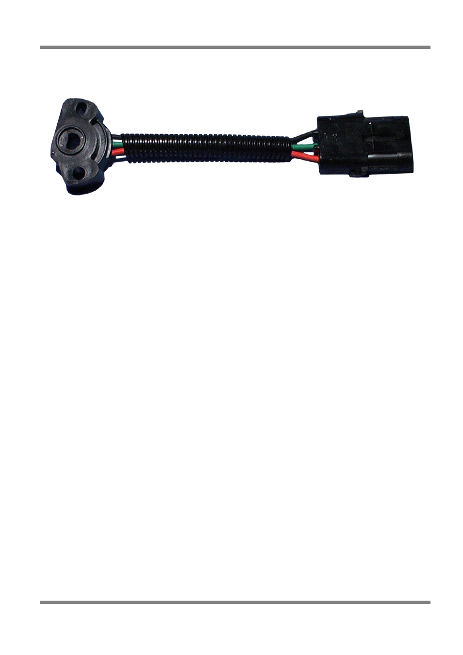
Figure 4 - Throttle Position Sensor
The throttle position sensor is mounted to the throttle butterfly shaft to measure its rotation. A TPS is
common on many late model engines and the Haltech sensor should attach with little or no modification.
The throttle shaft must protrude from the side of the throttle body. This may require the machining of the
throttle body or the manufacture of a new throttle shaft. The inner mechanism of the sensor rotates with
the shaft. If the shaft is round then file a flat surface on the shaft so that it will pass through the sensor
assembly. The TPS should be mounted against the side of the throttle body, using two screws, such that
the throttle shaft and the sensor mechanism can rotate freely. The absolute range of sensor movement is
not important as the sensor can be calibrated using the programming software.
Your engine may have a Throttle position sensor already fitted and it is often possible to make use of this
TPS. The Haltech supplied TPS has a resistance value ranging from 0 to 10k
Ω
. The resistance value of
the installed TPS does not have to be the same since the ECU uses a throttle calibration function to
determine the position of the throttle based on the signal received from the TPS. Be sure to wire the TPS
so that the ECU sees a lower value when at zero throttle than at full throttle.
Note: Make sure that the axis of rotation of the shaft is exactly aligned with the axis of rotation of the
sensor, otherwise some binding may occur. Also, do not use the TPS as a throttle stop. In either case, the
TPS will be damaged.
Ignition Modules
The Ignition Module should be mounted on a flat surface (eg. the firewall) to ensure proper heat
dissipation and to avoid stress on the wiring connections. It is also important to prevent the module
overheating by mounting it away from hot components such as exhaust manifolds and turbochargers.
Included with your ignition module, should be a wiring diagram for your ignition module. Follow the
directions on these instructions to connect your ignition module(s) to your main wiring harness. Locate the
ignition wires in the main loom. Using the supplied pins, crimp the pins onto the appropriate wires and
insert them into the appropriate locations in the ignitor plug, but do not connect it to the ignitor until the
ignition settings in the ECU are verified by connecting the ECU to a computer with Haltech programming
software.
Copyright © Haltech 2008
Page: 13