Haltech E8 User Manual
Page 16
Haltech E11/E8 Instruction Manual
There are two main types of sensor used for this application;
Reluctor Sensor Types
Variable Reluctance Transducers (VRT or simply reluctor) – this kind of sensor produces a sine wave
output. Generally a VRT sensor will have only 2 wires (a third wire may be present but its generally a
shield wire to help protect the signal from “noise”).
VRT sensors DO NOT require a power supply, they will have a signal wire and a ground wire only, the
way they work is almost the opposite of an electric motor with only one brush where the sensor has a
magnet inside with a coil of wire wrapped around it. As a ferrous material passes by the magnet the
magnetic field is disrupted and a voltage spike is created in the coiled wires surrounding the magnet
producing a sine wave. This signal is what is fed into the ECU. The ECU cannot interpret a sine wave
directly and must first process the sine wave into a digital signal before it is able to use this information.
The part of the ECU hardware that conditions the reluctor signal is called a reluctor adapter and it converts
the reluctor signals shown above to a square waveform similar to that of the Hall effect trigger. The
reluctor adapter and its tuning is dealt with in detail further later on.
Hall Effect Sensor Types
The second type of sensor found of crank and camshafts known as a Hall Effect (this includes optical
sensors) sensor. This style of sensor has a transistor and some electronics built into the sensor itself and
will generally require a power supply and ground of some sort. For this reason a hall effect sensor usually
has at least 3 wires. The output of this style of sensor is a digital square wave.
Page: 16
Copyright © Haltech 2008
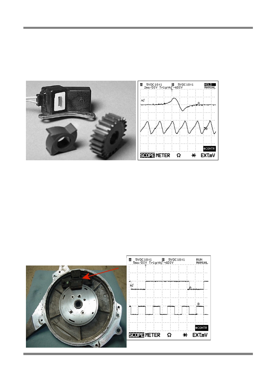
Figure 9: Reluctor Style Sensor
Figure 10: Reluctor Scope Trace
Figure 11: Hall Effect Sensor (Optical)