Wiring injectors, Wiring ignition – Haltech E8 User Manual
Page 18
Haltech E11/E8 Instruction Manual
Wiring Injectors
When wiring fuel injectors all Injectors share a common +12V supply voltage with the ECU INJ output
supplying the ground for the injector when fuel delivery is required. It is also essential for the +12V supply
voltage to the injector to be the same +12V supply that goes to the ECU. If using the Haltech long flying
lead harness this is already preterminated, if you are wiring your own harness you will need to ensure you
make this connection.
When wiring E8 or E11 for sequential fuel injection, fuel injectors should be wired with inj1 output to
cylinder 1, inj2 output to cylinder 2 and so on, the injectors firing sequence will be set in the software via
the firing order found on the advanced tab of the main setup page. If semi-sequential injection mode is
used the injection sequence will always be Inj1, inj2, inj3 inj 4 etc regardless of the firing order set in the
software.
Wiring Ignition
See below for some tables describing typical ignition wiring layouts
On the E8 and E11v2 ECU’s an external ignition amplifier (otherwise known as an ignition module, an
ignitor or ignition power transistor) is required. Some Ignition coils have these modules built into the coil
itself, others do not. As a general rule of thumb any coil with only 2 wires does NOT have the ignition
module built into it, you will need an additional ignition amplifier on these coils. If in doubt of your ignition
module requirements call your Haltech representative or the manufacturer of the ignition system.
When wiring E8 or E11 for direct fire ignition, ignition outputs should be wired with ign1 output to cylinder
1, ign2 output to cylinder 2 and so on, the ignition firing sequence will be set in the software via the firing
order found on the advanced tab of the main setup page. If wasted spark ignition is used the ignition
sequence will always be Ign1, ign2, ign3 ign 4 etc regardless of the firing order set in the software.
Distributor Ignition
Distributor ignition output is always on IGN 1.
Twin Distributor Ignition
Ignition output will always appear on IGN 1 and IGN 2 channels. In the majority of cases, IGN 1 will be the
first output to fire.
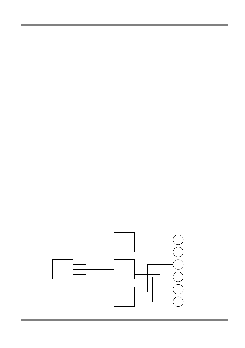
Waste Spark Ignition
When setup for waste spark ignitions, the order of the ignition outputs is simply in the order of the outputs.
IGN 1 will fire first, then IGN 2 will fire next etc until the last ignition channel is reached regardless of
engine firing order. The following example is for a 6-cylinder engine that fires 1-5-3-6-2-4.
Figure 13 - Waste Spark Ignition Configuration
Page: 18
Copyright © Haltech 2008
1
2
3
4
5
6
Ignitor
+ Coil
1
Ignitor
+ Coil
2
Ignitor
+ Coil
3
ECU
IGN1
IGN2
IGN3