Haltech E8 User Manual
Page 93
Haltech E11/E8 Instruction Manual
•
L
Used to linearise between two points.
•
V
Used to change the value in a cell or multiple selected cells.
Other
•
Ctrl T Opens throttle pump setup page without having to open fuel setup.
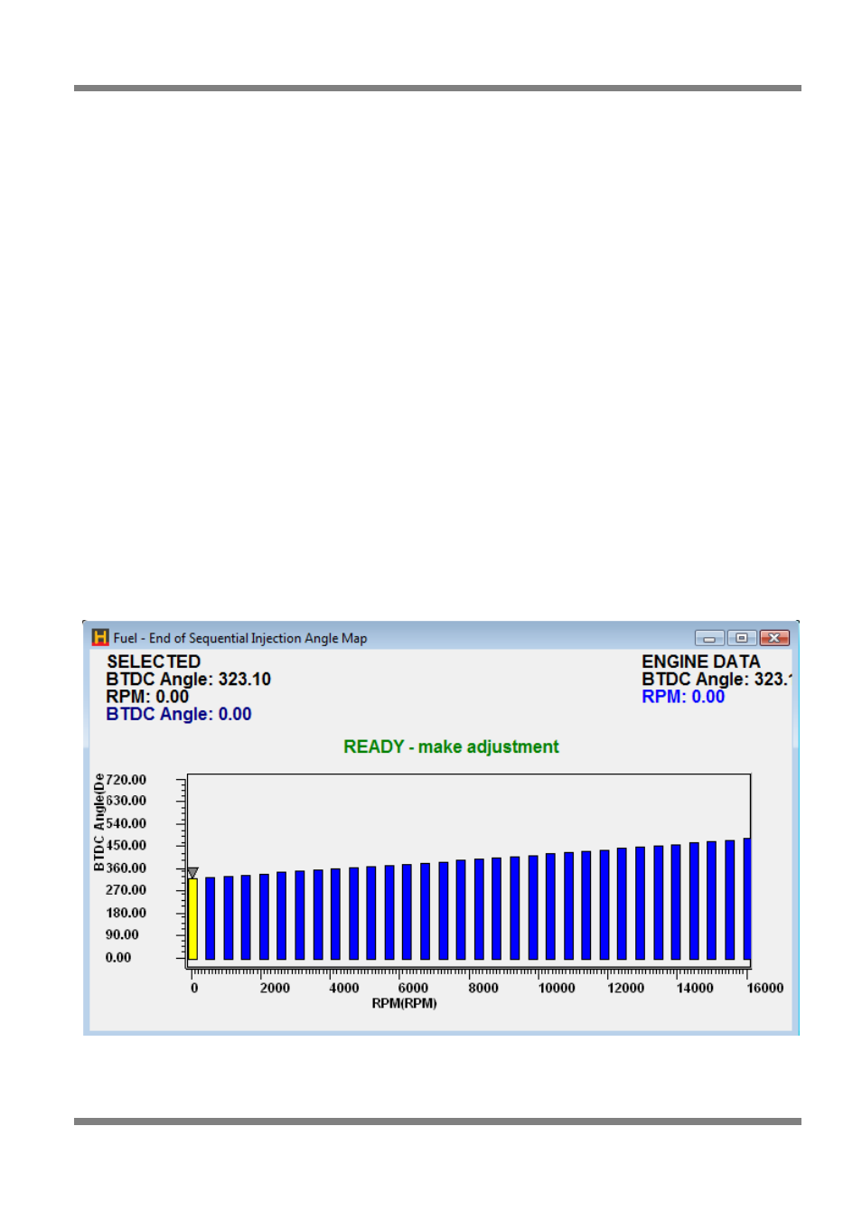
Injector Phasing Map – for Sequential Fuel Injection
The timing (or phasing) of sequential or semi-sequential injections is set via the Injector Phasing Map.
If the Injection Angle field is set to ‘End of Injection’, then this map sets the End of Injection angle, in
degrees BTDC compression, against the engine speed. This allows the injection to be completed before
the inlet valve opens. The ECU then times the start of injection, based on the trigger, so that the injection
is completed by the specified engine angle. If the ECU calculates that there is insufficient time to complete
injection before the specified End of Injection time, then injection will continue past this time.
If the Injection Angle field is set to ‘Beginning of Injection’, then this map defines the angle at which the
injection will begin BTDC compression. This mode is not often used, as the varying pulse width of the
injections will not ensure that the injection pulse finishes before the valve closes. This could lead to fuel
sitting in the manifold without any airflow to keep the fuel in suspension.
Engines with conservative cam profiles will notice very little difference between the injector phase angle
settings.
For 4-stroke engines, the typical usable range for injection angle is from 180 to 540 degrees BTDC.
For rotary engines, the typical usable range for injection angle is from 90 to 270 degrees BTDC. Any
angles greater than 360 degrees will be interpreted as 360 degrees BTDC.
Figure 96 - Sequential Injection End of Injection Map
Copyright © Haltech 2008
Page: 93