Futaba 18MZ 2.4GHz User Manual
Page 25
25
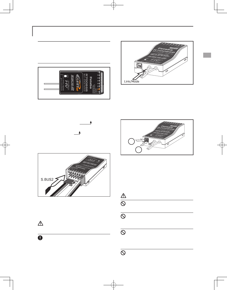
Link/Mode Switch
Use the small plastic screw driver that was
included with your receiver.
The Link/Mode Switch is also used for the CH
mode selection.
(The button is not used to link the transmitter
and receiver together. )
Extra Voltage Connector
Use this connector when using a voltage
telemetry device to send the battery voltage (DC0 ~
70V) from the receiver to the transmitter.
Please use an option is External voltage input
cable. Wire in an extra connector to you drive
batteries that mates with the extra voltage connector.
Danger
Don't touch wiring.
* There is a danger of receiving an electric shock.
Do not short-circuit the battery terminals.
* A short circuit across the battery terminals may cause
abnormal heating, fire and burns.
Please double check your polarity ( + and -)
when hooking up your connectors.
* If + and - of wiring are mistaken, it will damage, ignite and
explode.
Don’t connection to Extra Voltage before
turning on a receiver power supply.
Receiver nomenclature
Before using the receiver, be sure to read the
precautions listed in the following pages.
Receiver R7008SB
Connector
"1 through 6": outputs for the channels 1 through 6
"7/B": outputs of 7 channels and power.
"8/SB": outputs of 8 channels or S.BUS port.
[S.BUS Sevo S.BUS Gyro ]
"S.BUS2": outputs of S.BUS2 port.
[Telemetry Sensor ]
*When using 9 or more channels, use an S.Bus
function or use a second R7008SB and link both to
your transmitter.
Connector insertion
Firmly insert the connector in the direction
shown in the figure. Insert the S.BUS2 by turning it
90 degrees.
Warning
S.BUS2 connectors
Don't connect an S.BUS servo / gyro to BUS2
connector.
LED Monitor
This monitor is used to check the CH mode of
the receiver.