Bl-u2, N-42, Viii – KEYENCE BL-700 Series User Manual
Page 9
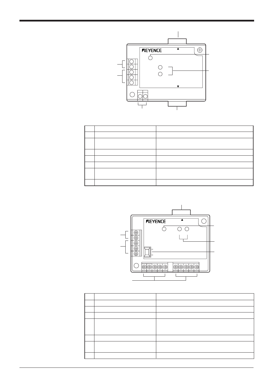
BL-U2
POWER
SD
RD
BL-U2
RS-232C
READER
7 RS-232C port
1 READER port
2 TRIGGER input
terminals
3 OK/NG output
terminals
4 Power supply
terminals
5 POWER LED
6 Communication
status indicator LEDs
5 Terminator switch
1 READER port
4 Power supply terminals
7 POWER LED
6 Communication
status indicator
LEDs
ON
OFF
2 TRIGGER input
terminals
3 OK/NG output
terminals
POWER
SD
RD
READER
N-42
No. Name
Function
1
READER port
Connects to a BL series or RS-232C equipment.
2
TRIGGER input terminals
Connect to a sensor for trigger input.
3
OK/NG output terminals
Output OK/NG signals.
4
Power supply/ interface
The 24 VDC power supply terminal and communi-
terminal block
cation interface (RS-422A or RS-485) terminal are
provided.
5
Terminator switch
Turns ON/OFF the terminator resistor: 100 ).
6
Communication status
Indicates the RS-422A or RS-485 communication
status.
7
POWER LED
Lights when the power is turned ON
No. Name
Function
1
READER port
Connects to a BL series bar code reader.
2
TRIGGER
Connect to a sensor for input terminals
trigger input.
3
OK/NG output terminals
Output OK/NG signals.
4
Power supply terminals
Connect to a 24 VDC power supply.
5
POWER LED
Turns on when the power is on.
6
Communication status
Indicate the communication status of the RS-232C.
indicator LEDs
7
RS-232C port
Connects to a personal computer, etc.
viii