3 wiring the keyence power supply unit bl-u2/n-42, 1 connecting the power supply, 2 connecting the bl-700 to bl-u2/n-42 – KEYENCE BL-700 Series User Manual
Page 30: Caution
Chapter 2 Connection and Installation
2
16
24 VDC
+
+
–
24V DC IN
24 VDC
+
+
–
24V DC IN
N.C. N.C. N.C.
CAUTION
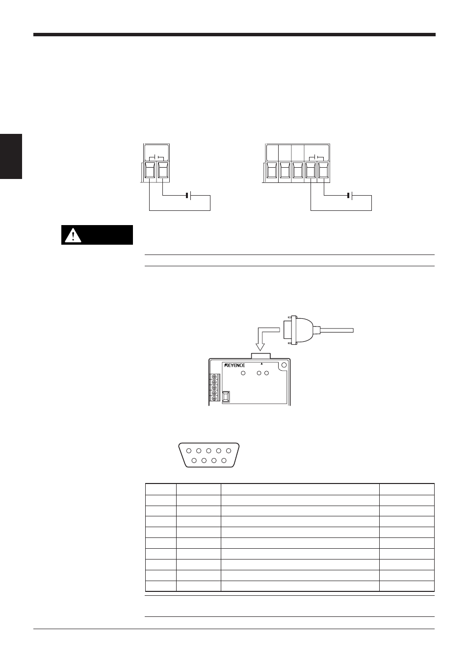
D-sub 9-pin (male)
DCE specification (defined as terminal)
#4-40 screw (female)
1
2
3
4
5
6
7
8
9
POWER
SD
RD
READER
2.3
Wiring the KEYENCE Power Supply Unit BL-U2/N-42
To use the BL-U2/N-42, connect as indicated below.
2.3.1 Connecting the power supply
Connect BL-U2/N-42 to a 24 VDC power supply.
BL-U2
N-42
Make sure that the power supply provides 24 VDC. If the power supply output
is not 24 VDC, it can damage the unit.
Note: If the power supply is UL rated, it must provide Class 2 output.
2.3.2 Connecting the BL-700 to BL-U2/N-42
Connect the BL-700 to the READER port of the BL-U2/N-42.
■ READER port pin assignment
Note: Do not extend a power cable. A long power cable can cause a voltage drop,
preventing the BL-700 from starting properly.
Pin No.
Symbol
Function
Signal direction
1
TIM
Trigger input
Output
2
RD (RXD)
Receives RS-232C data
Output
3
SD (TXD)
Sends RS-232C data
Input
4
OK
OK signal
Input
5
GND (SG)
Ground (Common ground for respective signal)
—
6
NG
NG signal
Input
7
RS (RTS)
Ready to send RS-232C data
Input
8
CS (CTS)
Request to send RS-232C data
Output
9
+5 V
5 V power supply output
Output