4 terminal, 5 connecting rs-232c (bl-u2), Pin assignment – KEYENCE BL-700 Series User Manual
Page 32: Wiring the rs-232c cable, Chapter 2 connection and installation, One connector is provided
Chapter 2 Connection and Installation
2
18
5 mm max.
6 mm min
2.0 mm
max.
1
2
3
4
5
6
7
8
9
Pin No.
Symbol
Description
Signal direction
2
RD (RXD)
Receive data
Input
3
SD (TXD)
Send data
Output
4
ER (DTR)
Connected to pin No.6 inside.
Output
5
SG
Signal ground
—
6
DR (DSR)
Connected to pin No.4 inside.
Input
7
RS (RTS)
Request to send data (always ON)
Output
8
CS (CTS)
Enable to send data
Input
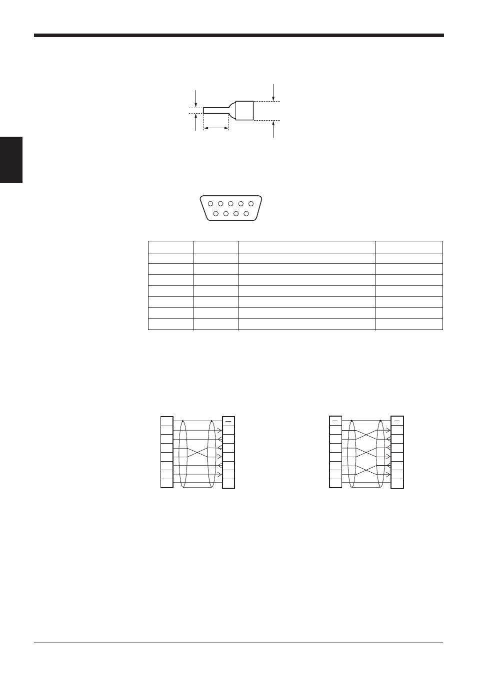
2.3.4 Terminal
A solderless contact pin, as shown below, is available for connection.
2.3.5 Connecting RS-232C (BL-U2)
Pin assignment
* One connector is provided.
Wiring the RS-232C cable
■ Connecting a PC
25-pin serial port
9-pin serial port
D-sub 9-pin (male)
DTE specification (defined as terminal)
#4-40 screw
2
PC
RD
SD
FG
ER
SG
DR
CS
RS
3
4
5
6
2
1
BL-U2
RD
Connector case
SD
DR
SG
RS
CS
ER
3
7
8
4
6
5
20
7
D-sub 25-pin (male)
M2.6 screw
D-sub 9-pin (female)
#4-40 screw
* KEYENCE option OP-22149 (1.5 m)
or OP-25057 (conversion connector)
can be used.
* KEYENCE option cable OP-27937 (1.5
m) can be used.
2
PC
SD
RD
DR
SG
ER
CS
RS
3
7
8
4
2
BL-U2
RD
Connector case
SD
DR
SG
RS
CS
ER
3
7
8
4
6
5
6
5
D-sub 9-pin (female)
#4-40 screw
D-sub 9-pin (female)
#4-40 screw
Connector case