3 device assignment – KEYENCE BL-700 Series User Manual
Page 123
109
Chapter 6 PCL Link
6
6.3
Device Assignment
The data areas used to control the BL-700 are provided in the PLC’s internal
memory (D areas or DM areas).
When a device head address is specified on the “PLC SETUP” screen in the BL-
700 setup software, the device numbers are automatically assigned based on the
specified head address.
Data memory head address
[Specified head address] +00 indicates the area where the bar code data is stored.
[Specified head address] +01 to +03 are reserved areas and cannot be assigned
for the bar code data.
[Specified head address] +04 to +06 are the areas used by the PLC to send a
reading trigger to the BL-700. The method for using the areas varies depending on
the BL-700 scan method, “Level signal trigger” or “One-shot signal trigger”. These
areas are not assigned if you set “Reading trigger input area” to “Disable” in the
BL-700 setup software. (In this case, these areas can be used for other purposes.)
When using the BL-700 in multi-label read mode 3, addresses +00 to +03 are used
as the data memory head addresses for Codes 1 to 4, respectively. Data is not
stored in the areas for which the code type is not set.
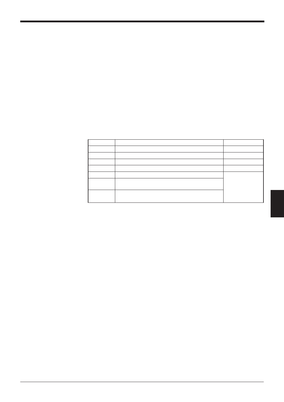
Address
Description
Reference page
+00
Data memory head address for Code 1
P.111
+01
Reserved area for Code 2
P.111
+02
Reserved area for Code 3
P.111
+03
Reserved area for Code 4
P.111
+04
Reading trigger area
P.111 to 113
+05
Reading trigger response area
* Only when “Level signal trigger” is selected.
+06
One-shot trigger time setup area
* Only when “One-shot signal trigger” is selected.