Appendix f sample program for the plc link, Appendices – KEYENCE BL-700 Series User Manual
Page 146
Appendices
132
Appendices
Appendix F Sample Program for the PLC Link
The sample program stores the read data in D105 (DM105) and subsequent DMs.
You can change the program to suit your application.
Before using the sample program, check that your system meets the following
requirements.
■ BL-700 settings
•
The scan method is “level signal trigger”.
•
Use the “PLC trigger area”.
•
The DM head address is “0000”.
■ Processing of data memory flag ... Sequential processing
*
This sample program uses the level signal trigger. However, it does not use the
+05 trigger input response area to check if the BL-700 successfully recognized
the +04 reading trigger area.
Data stored in D105 and
subsequent areas is processed.
2008
#0100
DW
DM0100
END
ENDH
0000
#0001
DW
DM0004
0000
#0000
DW
DM0004
#0002
DW
DM0100
2002
2010
DM0100
LDA
#0003
CMP
#0102
DW
DM0100
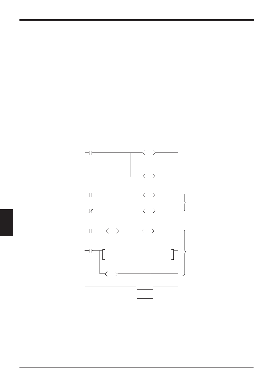
■ Program for the KV Series
Specify the head address of the
data memory area.
(Enter “2” in the data memory
flag. Use sequential processing to
process the flag.)
Enter “0000” for the reading
trigger input.
When DM0100 becomes “3”, the
specified processing is per-
formed.
After processing is completed,
enter “2” in DM0100.