Bl-u1 – KEYENCE BL-700 Series User Manual
Page 8
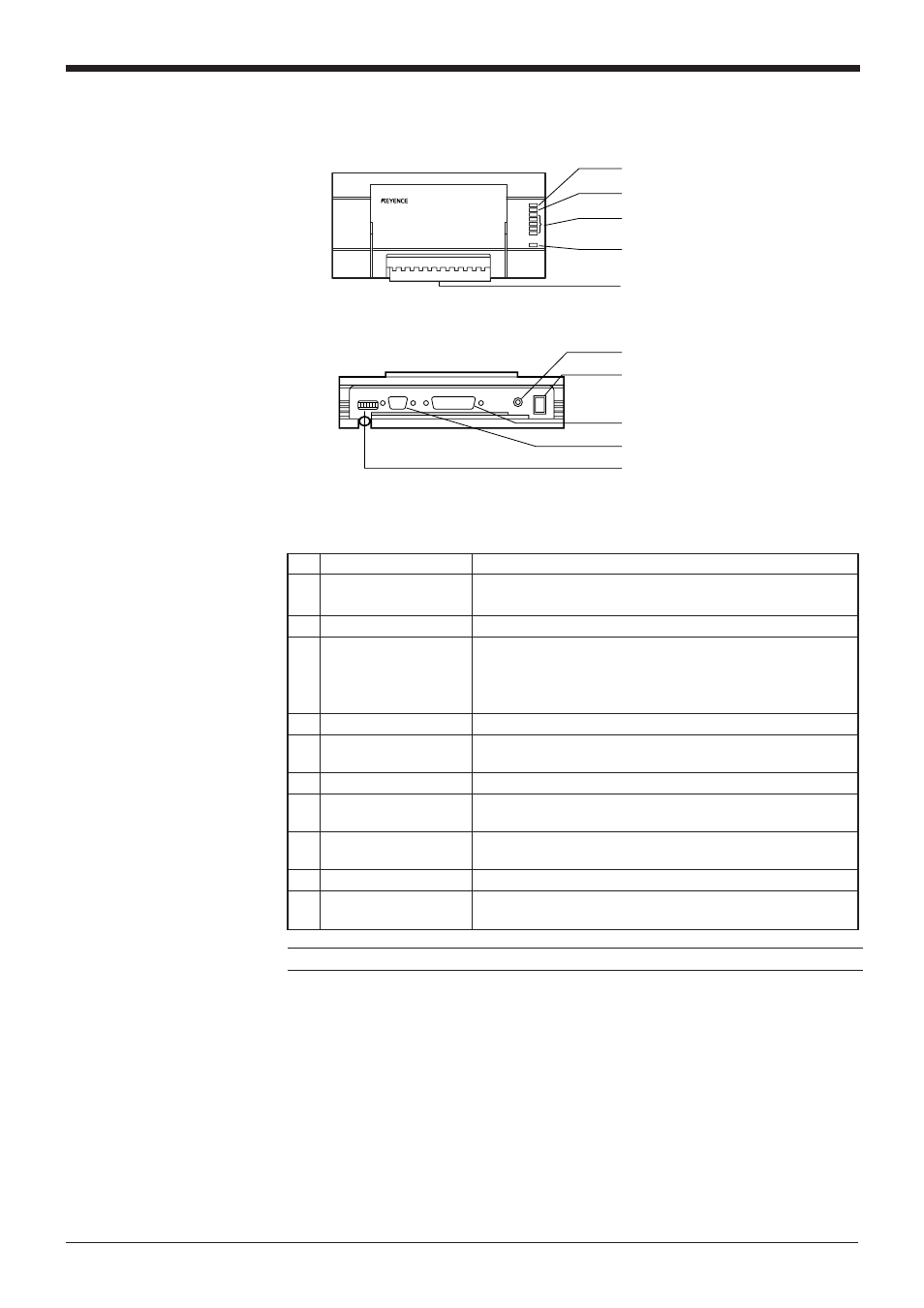
No. Name
Function
1
OK/NG LED
• When OK output is ON: The green LED lights.
• When NG output is ON: The red LED lights.
2
TIMING LED
Lit when trigger input is ON.
3
• Allows you to monitor the communication status of the
RS-232C port.
• The SD, RD, RS and CS indicators are provided in this
order from the top.
4
POWER LED
Lit when power is ON.
5
I/O terminal block
Includes the trigger input terminal, OK/NG output terminals,
RS-422A terminal and RS-485 terminal.
6
Power switch
Turns the power ON/OFF.
7
Use a 100 to 240 VAC (50/60 Hz) power supply.
8
RS-232C port
Connect a personal computer to this port. This port is
unused in multi-drop link mode.
9
READER port
Connect the BL series to this port.
0
DIP switches
Switches the communication port, and turns the terminator
ON/OFF.
Communication status
indicator LEDs
Power supply cable
(2 m)
BL-U1
1 OK/NG LED
2 TIMING LED
3 Communication status indicator
LEDs
4 POWER LED
5 I/O terminal block
6 Power switch
7 Power supply cable (2 m)
8 RS-232C port
9 READER port
0 DIP switches
vii
Note: This product does not comply with EC directives.