1 bl-700 connections, 1 connector pin assignment, 2 power supply connections – KEYENCE BL-700 Series User Manual
Page 20: Caution
Chapter 2 Connection and Installation
2
6
2.1
BL-700 Connections
This section describes connections when a KEYENCE power supply unit is not
used.
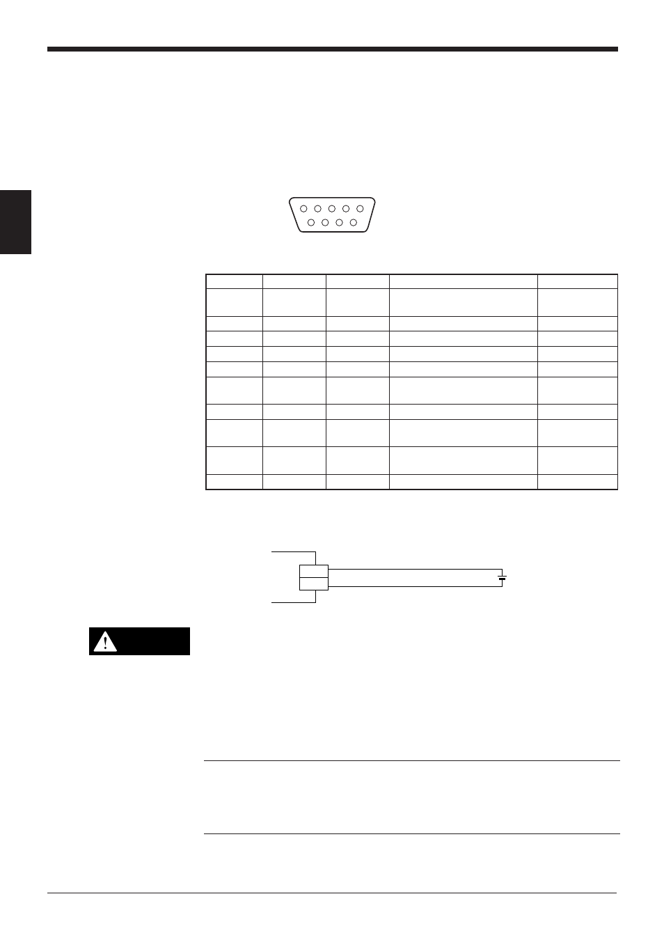
2.1.1 Connector pin assignment
The BL-700 connector has the following pin assignment.
D-sub 9-pin (female)
DTE specification (defined as terminal)
#4-40 screw (male)
1
2
3
4
5
6
7
8
9
2.1.2 Power supply connections
•
Be sure to match the polarities of the power supply when soldering the
connections. Reversing the polarities will damage the unit.
•
Make sure that the power supply provides a stable 5 VDC ± 5%. If the
power supply does not function in the above range, it can damage the unit.
•
Do not extend the power cable. A long power cable can cause a voltage
drop, preventing the BL-700 from starting properly.
Note: • Use the power supply that provides Class 2 output defined in NFPA 70
(NEC: National Electrical Code) when using this product as an UL certified
product.
• Use the Limited Power Source defined in UL/IEC60950-1 to comply with UL/
IEC60950-1.
Pin No.
Cable color Symbol
Description
Signal direction
Connector
Shield
FG
Frame ground
—
case
1
Yellow
TIM
Trigger input
Input
2
Brown
RD (RXD)
Receives RS-232C data
Input
3
Purple
SD (TXD)
Sends RS-232C data
Output
4
White
OK
OK output
Output
5
Black
GND (SG)
Ground (common ground for
—
respective signals)
6
Gray
NG
NG output
Output
7
Pink
RS (RTS)
Request to send RS-232C data Output
(always ON)
8
Blue
CS (CTS)
Enable to send data through
Input
RS-232C
9
Red
+5 V
+5 V DC power supply
Input
5 VDC
BL-700
+5V
9
GND
5
+
CAUTION