KEYENCE BL-700 Series User Manual
Page 54
Chapter 3 Functions for Reading Operation
40
3
The BL-700 continues to read the data while the laser beams scan the bar codes.
Thus, the STABILITY LEDs are not ON. When the bar code reading stops for 0.2
seconds, the BL-700 stops scanning and turns ON the STABILITY LEDs.
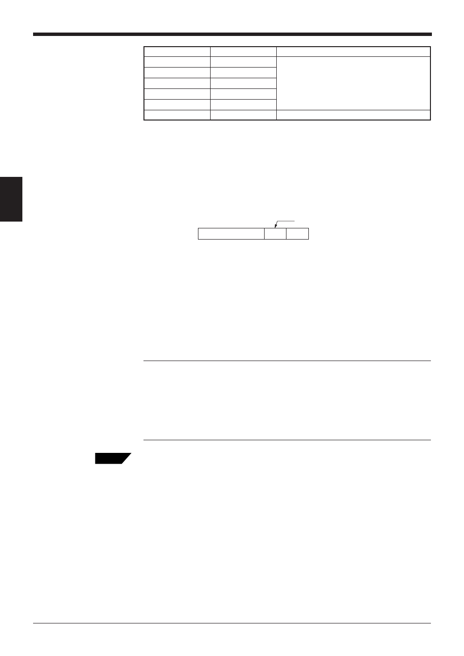
4. In the serial communication mode, the BL-700 outputs the data in the following
format.
By connecting the unit to a PC and using the BL setup software terminal, the
following data can be displayed on the PC screen.
➮ See P.77 for details of operation.
*
ON/NG LED turns ON but OK/NG output does not turn ON.
*
A value greater than 9999 cannot be added.
5. When reading the same bar codes continuously within 0.2 seconds, the BL-700
cannot separate the data and continues scanning to add the readout count.
When reading different bar codes within 0.2 seconds, continuous scanning is
enabled.
6. Press the TEST switch again to exit the test mode.
Note 1: When the unit is running in test mode, the laser beam remains on, which
can shorten the laser’s service life.
Select the test mode only when you need to perform a test read. Avoid long emis-
sion times.
Note 2: When using the “additional information” (
➮ see P.46 to 47) in the test
mode, the selected data is added in the same manner as in the normal operation
mode. However, only when selecting the reading rate check mode, the decode
count and scan count are not added to the analyzed results.
To start the test mode, the following alternative method is available in addition to the
method of using the TEST switch.
•
Start the test mode using the serial commands (
➮ see P.89)
Send the test mode start command (TEST1, TEST2) to start the test command. By
entering TEST1 or TEST2 and pressing [RETURN] from the provided setup
software terminal, the test mode is started.
•
Start the test mode by turning the trigger input ON (
➮ see P.58)
Turning the timing input ON enables the setting to start the test mode. When this is
set, the trigger input cannot function normally. Also, startup using the serial command
is disabled.
Use the setup software to perform the settings.
•
Start the test mode by turning power ON (
➮ see P.58)
Setting is available to start the test mode immediately at power-ON.
Use the setup software to perform the settings.
Readout data
m
:
Delimiter
* m = 1 to 9999 (zero-suppressed)
Reading rate
STABILITY LED
OK/NG LED
100 or more
5 LEDs ON
50 to 99
4 LEDs ON
10 to 49
3 LEDs ON
5 to 9
2 LEDs ON
1 to 4
1 LED ON
0
–
Red
Tips
Green (The readout count equals or exceeds
the matching decode count.)
Red (The readout count is below the matching
decode count.)