KEYENCE BL-700 Series User Manual
Page 57
Chapter 3 Functions for Reading Operation
43
3
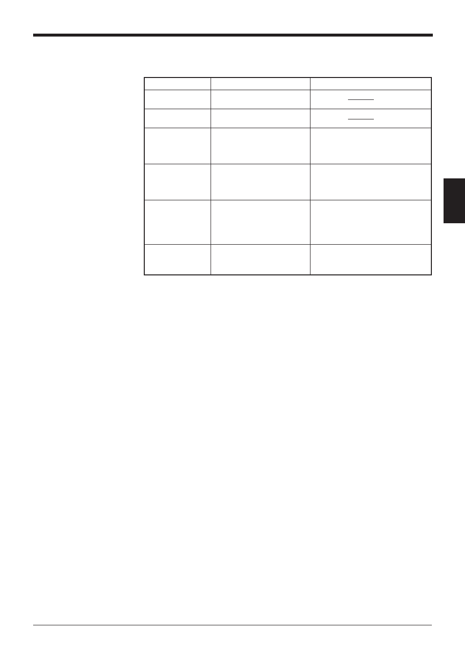
■ Unit operation status display
STABILITY LEDs indicate the following information in addition to reading stability.
Operation status
STABILITY LED display
Action to be taken
Power-on
LEDs turn on sequentially
from the bottom.
During setup
All the LEDs flash.
(
➮ see P.92)
Waiting for setting
The 1st, 3rd and 5th LEDs
In this status, send the settings from
data send/receive
from the top flash
the setup software. (Hold down the
(
➮ see P.73)
simultaneously.
TEST switch for 8 seconds to set the
data.)
Laser forced OFF
The bottom LED flashes.
When resetting laser forced OFF
(
➮ with LOCK
(with UNLOCK command), the unit
command,
returns to the initial operation at
see P.90)
power-on.
Unit error
Either of the 2nd, 3rd, or 4th
The unit may have failed or supply
LEDs from the top flashes.
voltage may have dropped. If supply
voltage is normal, the unit may have
failed. Contact the nearest
KEYENCE office or distributor.
PLC link error
The top LED flashes.
The error is reset by pressing the
(
➮ see P.117)
TEST switch again.
➮
See P.116 for troubleshooting.