6 wiring the rs-422a, Chapter 2 connection and installation – KEYENCE BL-700 Series User Manual
Page 28
Chapter 2 Connection and Installation
2
14
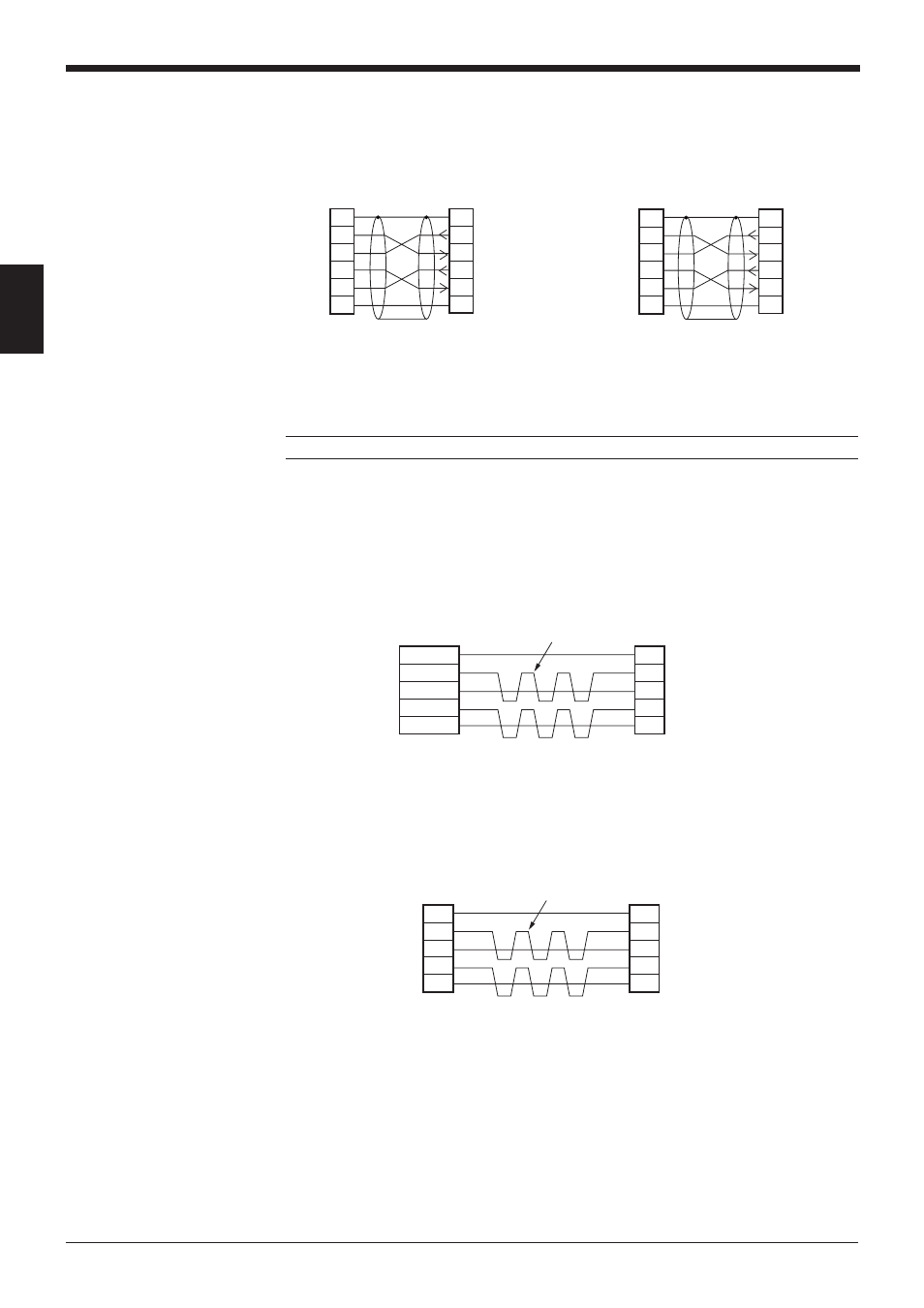
■ SYSMAC-CV series
Connection with CV500-LK201
(Port 1)
Note: BL-U1 is not available in Europe.
2.2.6 Wiring the RS-422A
Wire the RS-422A as indicated below.
■ Connecting a general RS-422A unit
Use the same wiring when connecting the BL-U1 to the BL-U1*.
•
Turn ON the terminators (BL-U1/external unit terminal resistance: 100 ).
➮ See P.35
.
•
The cable can be extended to within 1.2 km.
■ Connecting KV-L2*
Connecting the unit to RS-422A port 2
SDA
SG
BL-U1*
SDB
RDA
RDB
RD + (RDA)
SG
External unit
BL-U1*
RD – (RDB)
SD + (SDA)
SD – (SDB)
Twisted pair cable
SDA
SG
BL-U1*
SDB
RDA
RDB
RDB
SG
Link Unit
RDA
SDB
SDA
Twisted pair cable
Connection with CV500-LK201 (Port 2),
CV500,
CV1000,
CVM1
* KEYENCE option OP-22149 (1.5 m) or
commercially available cross cable can be
used.
2
Link unit
SD
RD
RS
CS
SG
3
4
5
7
2
1
1
BL-U1*
SD
FG
FG
RD
RS
CS
SG
3
4
5
7
D-sub 25-pin (male)
M2.6 screw
D-sub 25-pin (male)
M2.6 screw
2
PLC
SD
RD
RS
CS
SG
3
4
5
9
2
1
1
BL-U1*
SD
FG
FG
RD
RS
CS
SG
3
4
5
7
D-sub 25-pin (male)
M2.6 screw
D-sub 9-pin (male)
M2.6 screw