2 connecting bl-u1 and wiring, 1 connecting the power supply, 2 connecting the bl-700 – KEYENCE BL-700 Series User Manual
Page 22: Caution
Chapter 2 Connection and Installation
2
8
2.2
Connecting BL-U1 and Wiring
Note: This product does not comply with EC directives.
To use the BL-U1 AC power supply, connect it as described below.
2.2.1 Connecting the power supply
Plug the BL-U1 power cable into an outlet.
Use a power supply with 100 to 240 VAC ± 10% (50/60 Hz).
2.2.2 Connecting the BL-700
Connect the BL-700 to the READER port of the BL-U1.
The BL-U1 READER port pin assignment is as described below.
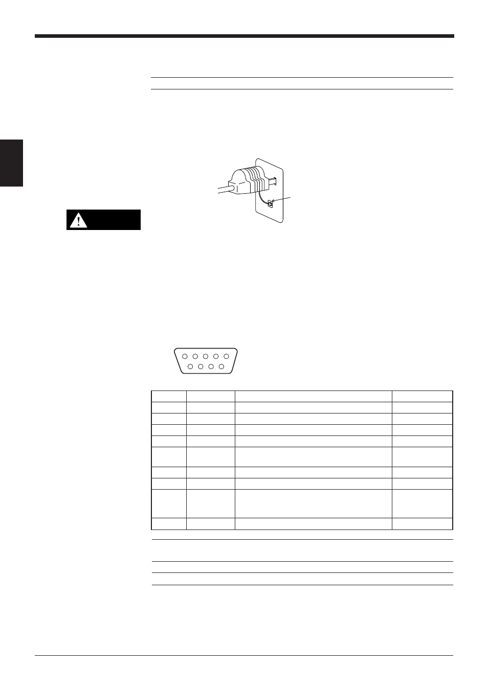
■ BL-U1 READER port pin assignment
FG line
CAUTION
Pin No.
Symbol
Function
Signal direction
1
TIM
Trigger input
Output
2
RD (RXD)
Receives RS-232C data.
Output
3
SD (TXD)
Sends RS-232C data.
Input
4
OK
OK
Input
5
GND (SG)
Ground (Common ground for respective
—
signal)
6
NG
NG
Input
7
RS (RTS)
Ready to send RS-232C data.
Input
8
CS (CTS)
Request to send RS-232C data.
Output
(Control method can be selected with the DIP
switches.)
➮ See p. 9.
9
+5 V
+5 V power supply
Output
D-sub 9-pin (male)
DCE specification (defined as terminal)
#4-40 screw (female)
1
2
3
4
5
6
7
8
9
Note: Do not extend a power cable. A long power cable can cause a voltage drop,
preventing the BL-700 from starting properly.
Note: This product does not comply with EC directives.