Dynojet 424x: Installation Guide User Manual
Page 74
In Ground Model 424x/424xLC
2
Automotive Dynamometer Installation Guide
C H A P T E R 3
Bridge Installation—Stationary Dyno
3-38
6
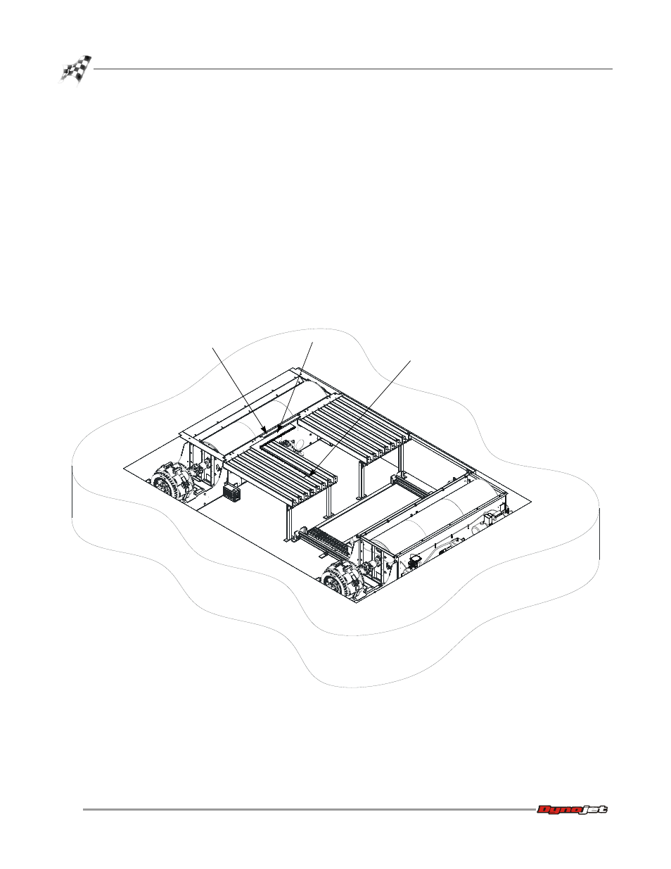
Square up the runner assemblies.
6a
Place a square ruler along the edge of the stationary dyno and along one of
the runner assemblies. Move the runner assemblies until they are square
with the dyno.
6b
Tighten the bolts securing the runner assemblies to the runner mounts.
6c
Tighten the bolts securing the runner mounts to the dyno.
7
Dynojet recommends you anchor the support pillars to the dyno room floor,
however this step is optional.
7a
Using the support pillars as a template, mark and drill each hole needed to
secure the four pillars to the floor.
7b
Install eight Red Head anchors. Refer to Appendix A for installation
instructions.
7c
Secure each pillar to the floor using two 3/8-16 x 1-inch hex-head bolts and
two 3/8-inch flat washers.
Figure 3-26: Square up the Runner Assemblies
AD382
edge of dyno
square ruler
runner assembly