Placing the dyno in the pit – Dynojet 424x: Installation Guide User Manual
Page 35
S T A T I O N A R Y D Y N O I N S T A L L A T I O N
Dyno Installation
Version 7
In Ground Model 424x/424xLC
2
Automotive Dynamometer Installation Guide
2-11
P
LACING
THE
D
YNO
IN
THE
P
IT
1
Using the forklift, gently lower the dyno into the pit.
Note: Make sure the dyno air brake is facing towards the center of the pit.
2
Gently lower the dyno into position.
3
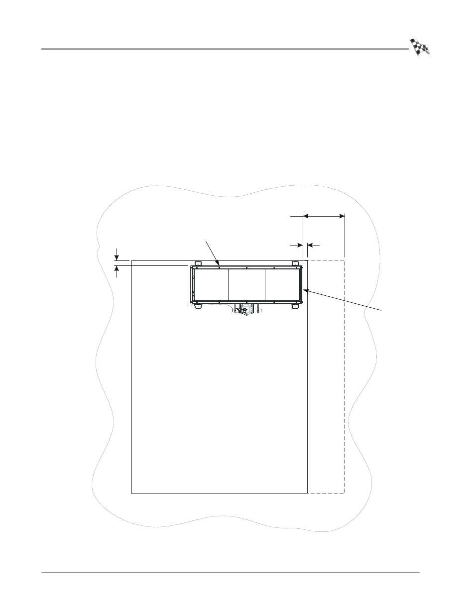
Verify the side of the dyno is 8.26 cm (3.25 in) from the pit wall.
When installing the Linx option, verify the side of the dyno is 118.75 cm
(46.75 in) from the pit wall. For more information on installing the Linx option,
refer to the Linx Installation Guide P/N 98200021.
4
Verify the rear of the dyno is 10.16 cm (4.00 in) from the pit wall.
Figure 2-4: Placing the Dyno in the Pit
AD427
eddy current
brake to be
installed here
8.26 cm
(3.25 in.)
10.16 cm
(4.00 in.)
vehicles loaded
from this end
rear of dyno
side of dyno
118.75 cm
(46.75 in.)
Linx option