Dynojet 424x: Installation Guide User Manual
Page 108
In Ground Model 424x/424xLC
2
Automotive Dynamometer Installation Guide
C H A P T E R 4
Load Cell Calibration
4-24
While installing the calibration weights, you should notice the Torque Gauge on the
DynoTrac Window moving from 0 to about 500 foot-pounds.
Note: The Torque Gauge may or may not be in this range.
• If the torque cell has been previously calibrated incorrectly or has not been
calibrated for a while, the gauge may show values out of this range until
calibration is complete.
Note: Let the torque gauge needle stabilize before clicking Next.
10 From the Span Calibration window (Figure 4-24), click Next to continue.
At this point, the value on the gauge should match the value on the calibration
arm.
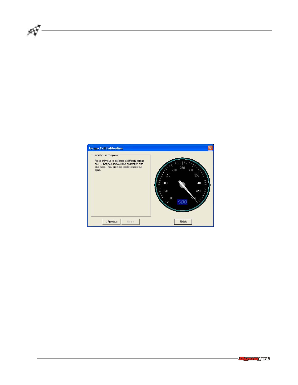
11 Click Previous to calibrate a different torque cell. Repeat steps 7-10.
12 Once you have completed calibrating the torque cell(s), remove the weights and
calibration arm(s) and click Finish.
Figure 4-27: Calibration Is Complete Window