Dynojet 424x: Installation Guide User Manual
Page 73
4 W D D Y N O I N S T A L L A T I O N
Bridge Installation—Stationary Dyno
Version 7
In Ground Model 424x/424xLC
2
Automotive Dynamometer Installation Guide
3-37
5
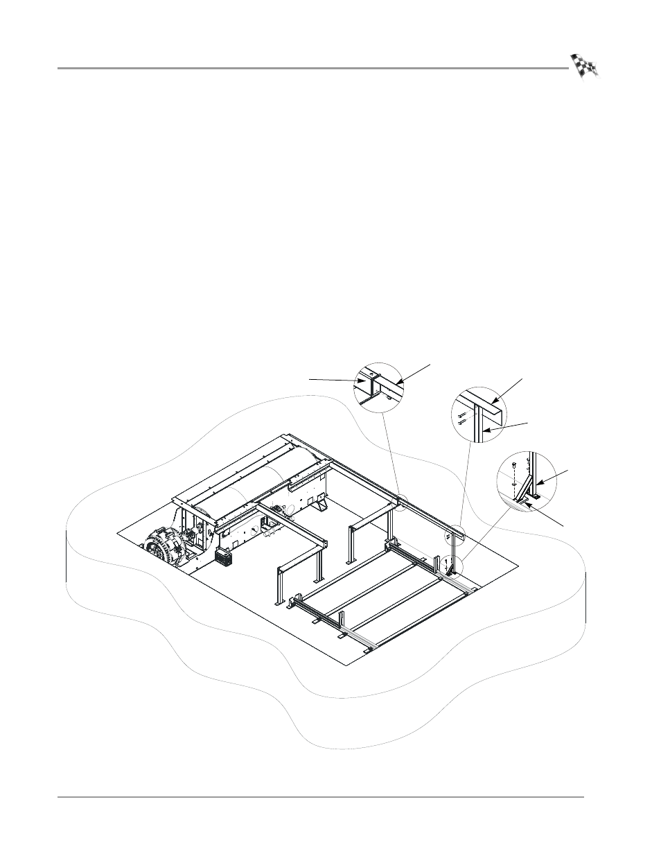
Install the runner extension. There is a left and right version of the runner
extension; the left version is shown in Figure 3-25.
Note: Do not install the runner extension on the side of the dyno where the eddy
current brake will be installed.
5a
Secure the support leg to the runner extension using two 1/4 x 1.5-inch
bolts, two flat washers, and two 1/4-20 nuts.
5b
Remove the two 1/4-20 torx screws from the runner assembly.
5c
Secure the runner extension to the runner assembly using the two torx
screws removed earlier.
5d
Remove the existing bolt securing the rail tie clip and secure the leg support
to the track using the existing bolt.
5e
Mark and drill the hole needed to secure the support leg to the pit floor.
5f
Install the Red Head anchors. Refer to Appendix A for installation
instructions.
5g
Secure the support leg to the floor with one 3/8 x 1-inch bolt and one flat
washer.
Note: For clarity, the 4WD dyno and eddy current brake not shown.
Figure 3-25: Install the Runner Extension
AD428
runner extension
runner assembly
support leg
runner extension
support
leg
track