Dynojet 424x: Installation Guide User Manual
Page 72
In Ground Model 424x/424xLC
2
Automotive Dynamometer Installation Guide
C H A P T E R 3
Bridge Installation—Stationary Dyno
3-36
I
NSTALLING
THE
R
UNNER
A
SSEMBLIES
AND
R
UNNER
E
XTENSION
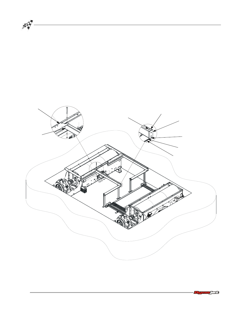
1
Place the plastic runner slide on top of the runner support.
2
Slide each runner assembly into the runner mount. Verify the plastic end faces
away from the stationary dyno.
3
Loosely secure each runner assembly to the runner mount using one 3/8 x 5-inch
bolt, flat washer, lock washer, and nut. These bolts will be tightened later.
4
Loosely secure each runner assembly to the runner support from underneath
using one 1/4 x 1.25-inch bolt and lock washer. These bolts will be tightened later.
Verify the existing bolt in each runner assembly is on top. There are sixteen
runner assemblies, eight with each runner mount.
Note: For clarity, only two runner assemblies are shown.
Figure 3-24: Install the Runner Assemblies
AD381
runner assembly
runner mount
runner
assembly
runner support
existing bolt on top
secure from underneath
(not visible from this view)
plastic end
runner slide