Routing the cables—with two eddy current brakes – Dynojet 424x: Installation Guide User Manual
Page 56
In Ground Model 424x/424xLC
2
Automotive Dynamometer Installation Guide
C H A P T E R 3
Cable Routing
3-20
R
OUTING
THE
C
ABLES
—W
ITH
T
WO
E
DDY
C
URRENT
B
RAKES
Use these instructions for routing cables with two eddy current brakes. Refer to
Chapter 4 for eddy current brake, torque module, and load cell installation
instructions.
Refer to Figure 3-13 for cable locations.
Refer to page 3-23 for more information on wiring the Advanced Breakout board.
You will need the following parts:
• DM150-009-003
Washer, 1/4", Flat (4)
• DM150-011-005
Bolt, 1/4" x 1/2", Hex (4)
1
Pull both the first and second cable tracks out from under the dyno.
2
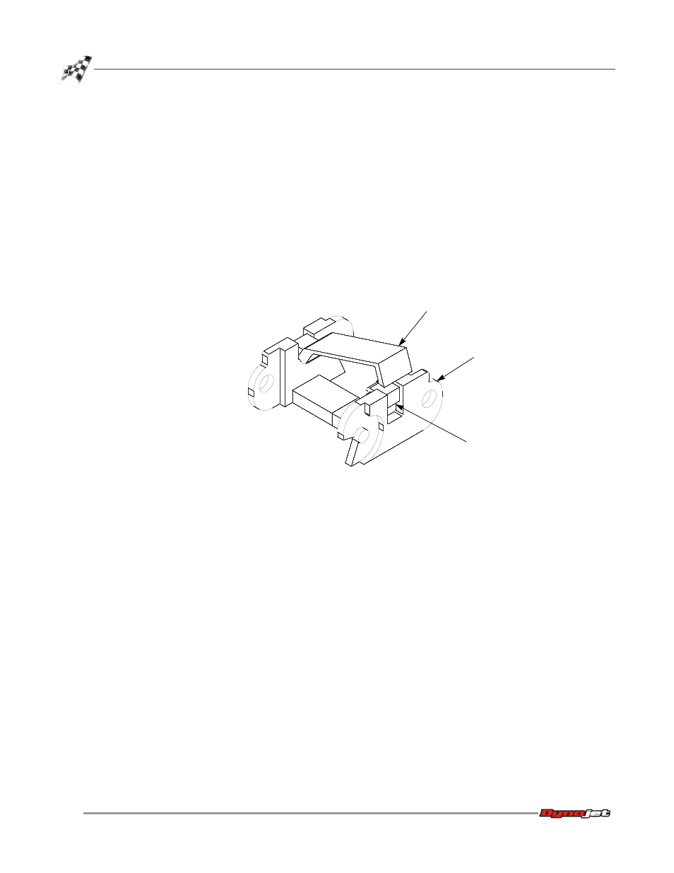
Using a screwdriver, open the crossbar on each link.
Figure 3-12: Open the Crossbar
3
Place the theta power cable (Q) in the second cable track with the air hoses.
4
Place the load cell cable (K), theta signal cable (M), and temperature sensor cable
(O) in the first cable track.
5
Close the cable door on each link.
6
Place the cable tracks back under the dyno.
7
Secure the first and second cable tracks to the front rail tie assembly using two
1/4-20 x 1-inch hex-head screws and two washers each.
8
Route the 25-pin cable (A) from the Advanced Breakout board, through the pit
conduit, and to the dyno electronics. Connect the 25-pin cable to the dyno
electronics.
Refer to Figure 1-6 for information on where to connect the 25-pin cable.
9
Route the pickup card cable (B) from the stationary dyno to the Advanced
Breakout board.
Route the pickup card cable (C) from the first cable track to the Advanced
Breakout board.
Refer to page 3-23 for more information on wiring the Advanced Breakout board.
AD079
cable track
link
crossbar
use screwdriver
to open