Figure 3-10 – Dynojet 424x: Installation Guide User Manual
Page 53
4 W D D Y N O I N S T A L L A T I O N
Cable Routing
Version 7
In Ground Model 424x/424xLC
2
Automotive Dynamometer Installation Guide
3-17
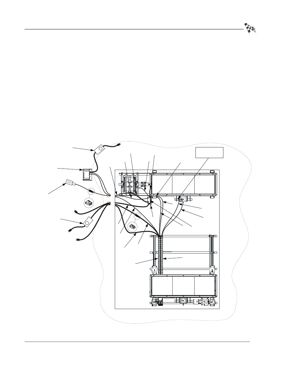
11 Route the theta signal cable (L) from the stationary dyno theta controller to the
Breakout board.
Refer to page 3-15 for more information on wiring the Breakout board.
12 Route the temperature sensor cable (N) from the stationary dyno eddy current
brake to the Breakout board.
Refer to page 3-15 for more information on wiring the Breakout board.
13 Route the theta power cable (P) from the stationary dyno, through the pit
conduit, and to your 240V power source.
14 Route the controller cable (R) from the eddy current brake to the theta controller.
Connect the cable to the theta controller.
15 Route the power cable (G) from the first cable track, through the pit conduit, and
connect to the power supply. Plug the power supply into your power source.
16 Connect the power supply to the dyno electronics. Plug the power supply into
your power source.
Figure 3-10: Routing the Cables—With One Eddy Current Brake
DRY AIR IN
100-140 PSI
AD391
E
C
D
dyno electronics
stationary
dyno
4WD dyno
first cable
track
F
power supply
dyno movement
pendant
power supply for
dyno electronics
breakout
board
second
cable track
J
G
I
B
P
A
N
L
theta controller
R
H