ADS Environmental Services IETG FlowHawk QR 775012 A4 User Manual
Page 256
Configuration and Activation 6-77
1. Select the Velocity 1, Peak Velocity 3, or Surface Velocity 3
from the Diagnose Device drop-down list, and then select the
Diagnose button. Velocity 1 represents the velocity sensor in
both the Peak Combo Sensor and the Slimline Peak Combo
Sensor, Peak Velocity 3 represents the surcharge peak velocity
sensor in the Surface Combo Sensor, and Surface Velocity 3
represents the surface velocity sensor in the Surface Combo
Sensor.
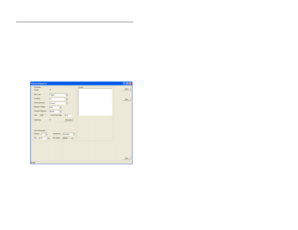
The Diagnostics dialog displays the current configuration
parameters stored in the LIF for the Velocity 1/Peak Velocity
3/ Surface Velocity 3.
Velocity Diagnostics dialog displaying the current parameters for the
Velocity 1 device
2. Click on the Read button.
The Results section displays the current velocity of the flow,
temperature, and other factors measured by the selected
velocity sensor.