ADS Environmental Services IETG FlowHawk QR 775012 A4 User Manual
Page 142
4-24
IETG FlowHawk Manual
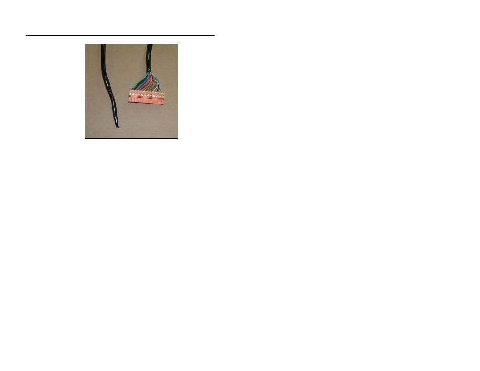
Forming a thin taper using vinyl tape
4. Excavate a trench at least 305 mm (12 in) deep and 102
millimeters (4 in) wide from the EMU/power source location to
the monitor location. Consult local regulations to verify the
required trench depth for the area.
5. Drill a 13-milllimeter (½-in) (minimum) hole through the corbel
(structural foundation holding the manhole cover) or manhole
wall to provide a smooth transition for the cable into the trench.
6. Run the communication cable from the monitor location in the
manhole to the EMU/power source location. If required by
local code, run cable through 19-millimeter (¾-in) electrical
PVC conduit in the following way:
Extend the conduit through the manhole corbel or wall at
the monitor location.
Lay the conduit in the trench per local regulations and feed
the communication cable through the conduit.
Extend the conduit approximately 305 mm (12 in)
vertically out of the trench (from the ground surface) at the
designated EMU/power source location.
Use urethane foam to seal the space between the conduit
and the corbel or manhole wall to prevent infiltration into
the manhole.