Lead extension cases, Center (fifth) harness cables, Dress cables – Great Plains NTA2007HD Predelivery Manual User Manual
Page 90: Umn (see step 350) f
86
Great Plains Manufacturing, Inc.
NTA607HD
166-283Q
02/09/2011
Lead Extension Cases
350. If the table “Lead Ext.” column has:
“+3ft” (91cm),
“+10ft” (3.0m) or
“+15ft” (4.6m)
Select a matching extension cable per the table
above right. Connect the extension to the lead.
Determine where to connect this extended cable,
based on the Appendix tables. An extended lead
connects to an adjacent tower. This is illustrated by
cable diagrams in the DICKEY-john® Quick Start
Guide.
Refer to Figure 154
351. For extension cables to a wing tower, route the
cable along the center frame to the primary hose to
the destination tower. Follow the primary hose along
the wing to that tower, using any hose loops pro-
vided.
For extensions to center section towers, see the
next topic.
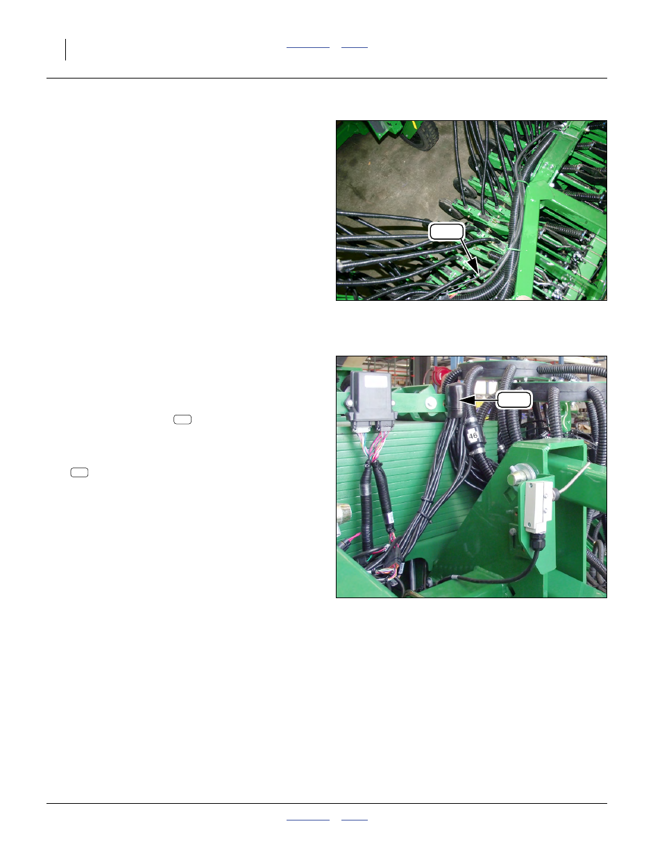
Center (Fifth) Harness Cables
Refer to Figure 155
40-row double-shoot implements have five WSMBs.
Center harness position 3
is on the center section,
and serves towers on both sides.
352. Leads from center harness, left to Tower F, require a
“+3ft” (91cm) extension:
459680920 EXT. HARNESS 3’, FAN RPM
Leads from center harness, right to Tower C, require
no extensions.
Route leads and extensions to avoid moving parts
(including lift assist link).
353. Use supplied cable ties to secure extension cable
runs to nearby primary seed hose or monitor har-
nesses.
Dress Cables
354. Using cable ties supplied, secure monitor harness
leads to frame tubes, primary seed hoses, tower
mounts and tower riser tubes.
355. Coil up excess sensor and monitor leads at each
tower. Secure with cable ties provided.
Null4:
Figure 154
Wing Lead Extension
Q0083
155
Null4:
Figure 155
Center Harness Sensor Leads
Q0082
160
160
154