Install row harnesses, Install row harnesses on towers, Install center section row harness – Great Plains NTA2007HD Predelivery Manual User Manual
Page 82
78
Great Plains Manufacturing, Inc.
NTA607HD
166-283Q
02/09/2011
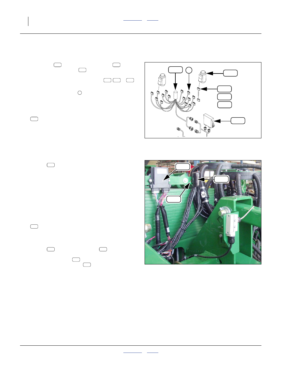
Install Row Harnesses
Row harnesses
collect blockage sensor
data
and present it to the WSMB
. Normally, the sensors
connected are located on the same tower as the row har-
ness - where they are not, an extension (
,
or
)
is provided.
Connection of sensor leads
is completed at “Connect
Install Row Harnesses on Towers
312. Select one of:
467751320S1 DJ 12 ROW HARNESS
or
467751330S1 16 ROW HARNESS
Note: Row harnesses vary with row spacing, hopper
count and single- vs. double-shoot. However, all
row harnesses on a single implement must be the
same part number.
313. Using two large cable ties provided in the
DICKEY-john
®
kit, secure the potted harness
module
to the tower tube. Orient the module:
• behind the plate bearing the WSMB,
• cables exiting downward, and
• top of the module about 13cm (5in) below turret.
Apply ties below the center of the module.
Repeat step 312 and step 313 for each tower.
Install Center Section Row Harness
Refer to Figure 142 (which depicts this area at a later stage
of assembly)
314. Select one of:
467751320S1 DJ 12 ROW HARNESS
or
467751330S1 16 ROW HARNESS
315. Using two large cable tie provided in the
DICKEY-john
®
kit, secure the potted harness
module
to the WSMB mount
. Orient the
module:
• rear face of mount
,
• right end slots of mount
, and
• cables exiting downward.
Apply ties below the center of the module.
Null4:
Null4:
Figure 141
Row Harness Elements
Q0081
167
159
152
160
154
155
2
160
159
167
152 154
155
160
Null4:
Figure 142
Center (5th) Row Monitor Harness
Q0082
130
167
160
160
160
160
130
130
130