Mount cart wheels – Great Plains NTA2007HD Predelivery Manual User Manual
Page 29
Great Plains Manufacturing, Inc.
Cart Assembly
25
02/09/2011
166-283Q
Mount Cart Wheels
Avoid Needless Spring Hazard:
Mount right rear cart transport wheel AFTER installing con-
tact drive (step 76 on page 24). If the transport wheel is
mounted prior to the contact drive, it is extremely difficult, and
possibly dangerous, to compress the spring rod enough to
allow contact drive installation.
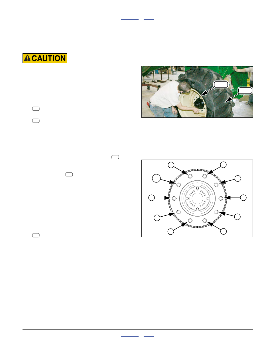
Refer to Figure 34
84. At each cart hub, remove and save ten sets of:
803-183C NUT HEX FLANGE 3/4-16 PLT
85. Select the left wheel assembly:
168-381K 23.5/55-26 TIRE/20-10BLT WL LH
Note: If the wheels are not clearly marked, use the follow-
ing guidelines for identifying left and right:
• valve stems are to the outside
• tread “V” patterns point forward at top
86. Jack up the rear end of the cart.
87. At the left cart hub, mount the LH wheel
with
valve stem side out.
Refer to Figure 35
88. Start all lug nuts
by hand, flange side of nut to
wheels. Choose a bolt stud to designate position #1.
89. Torque in stages, setting each lug nut to the speci-
fied torque in the order shown in the figure:
Stage 1: 27-33 N-M (20-25 ft-lbs)
Stage 2: 74-80 N-M (55-60 ft-lbs)
Stage 3: 114-127 N-M (85-95 ft-lbs)
Note: This staging and ordering of tightening is strongly
recommended to ensure that the brake drum is not
driven out-of-round.
90. At right hub, similarly install the right wheel:
168-380K 23.5/55-26 TIRE/20-10BLT WL RH
91. Check tire inflation (see 166-283M Operator man-
ual). Lower cart onto wheels. Block tires to prevent
roll-away.
Null4:
Figure 34
Mount Left Cart Wheel
Q0015
218
138
218
138
Null4:
Figure 35
Bolt Torquing Pattern
31385
3
7
9
2
4
6
1
5
8
10
138
218
137