Insert sensors, Adjust double-shoot tower, Insert sensors adjust double-shoot tower – Great Plains NTA2007HD Predelivery Manual User Manual
Page 88
84
Great Plains Manufacturing, Inc.
NTA607HD
166-283Q
02/09/2011
Insert Sensors
Start with Tower A, then complete towers B-D, and if dou-
ble-shoot; E-H.
Start with any port on the tower.
Refer to Figure 151
342. Gather the hose near the bottom of the dimpled
region of the tower tube. Mark a location on the
hose above that,
just below where the hose is fully vertical.
For most outlets, this is a distance of:
30cm (12in) from the turret.
For outlets passing over a lower turret, such as at
in Figure 152, use a longer distance as needed.
Repeat for all ports on tower.
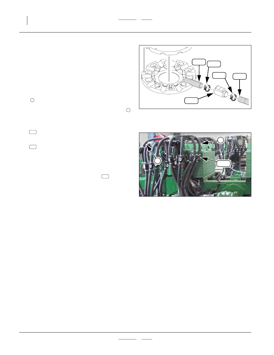
343. Cut one hose at the mark. Select the:
467420701 VIGILENSE BLOCK SENSOR 25MM
bearing the Drop No. of the port for that hose.
Select two:
800-123C CLAMP WRM DRV #16 SS (.68-1.5)
Slide the clamps onto each end of the sensor.
Note: Sensor orientation:
• directional arrow on sensor body pointing down
• cable exit on inside (near tower tube)
344. Insert cut hose ends into the sensor
, to the
ridges inside, a depth of:
2.5cm (1in)
Tighten clamps only until hoses are held securely.
Be careful not to crush hose or damage sensor.
Repeat step 342 through step 344 for all ports on tower,
and then all towers.
Adjust Double-Shoot Tower
For a single-hopper or single-shoot drill, skip step 345.
345. At each double-shoot (fertilizer) tower, adjust the
vertical position of the tower so that the top of the
turret cap is as close as possible to the underside of
the seed tower cap, without actually touching.
Secure the U-bolts for the fertilizer tower.
Null4:
Figure 151
Sensor Installation
31272
307
307
159
174
174
6
7
Null4:
Figure 152
Sensor Placement
Q0066
159
7
6
159
174
159