Install rear pull link, Release rear pull link, Connect rear pull link – Great Plains NTA2007HD Predelivery Manual User Manual
Page 40: Release rear pull link connect rear pull link
36
Great Plains Manufacturing, Inc.
NTA607HD
166-283Q
02/09/2011
Install Rear Pull Link
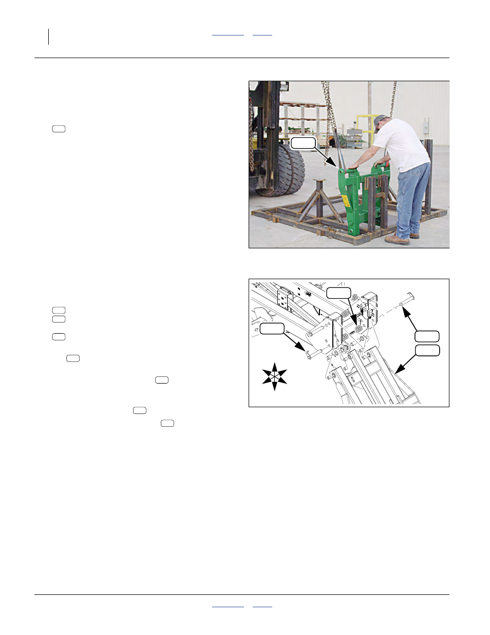
Release Rear Pull Link
Refer to Figure 55 (which depicts U-bolts already removed)
120. Support the cart-implement link:
160-316H NTA607HD REAR PULL LINK WELDMT
with at least two hoist straps.
As racked, the upper (wider) end of the cart-imple-
ment link is the caster (rear) end. A large lug (not
visible in Figure) will be down upon installation.
121. Remove the U-bolts securing the link to the rack.
These U-bolts are not re-used.
122. Position the link near the implement rear, front
(narrow) end toward implement and center lug side
down.
Null4:
Connect Rear Pull Link
Refer to Figure 56
123. Select two sets:
160-201H WING PIVOT PIN WELDMENT
805-255C PIN ROLL 3/8 X 2 1/2 PLT
and six:
804-039C WASHER FLAT 1 1/4 SAE PLT
124. Align the bushings at the front ends of the pull
link
tubes with the lower rear holes of the cen-
ter section weldment.
125. From the outside, insert pins
. Fully seat the
break in the pivot pin cap in the square hole of the
outside center section plate.
126. Add three (3) washers
to each pin.
127. Secure both pins with roll pins
(not shown).
Null4:
Null4:
Figure 55
Release Rear Pull Link
Q0043
111
111
Null4:
Figure 56
Connect Rear Pull Link
31259
108
U
D
L
R
B
F
108
232
111
108
247
232
111
247
232
247