Great Plains NTA2007HD Predelivery Manual User Manual
Page 71
Great Plains Manufacturing, Inc.
Implement Assembly
67
02/09/2011
166-283Q
Start with the hose letter (A or E) that passes
through the lower left position at the implement por-
tal, and work left-to-right, then up. Connect the
meter end of that hose to the meter outlet or Y-tube
manifold outlet of the same letter.
Seat each hose fully against the meter housing or
manifold plate. Position the clamp about 2cm (
3
⁄
4
in)
from the end of the hose. Tighten clamp.
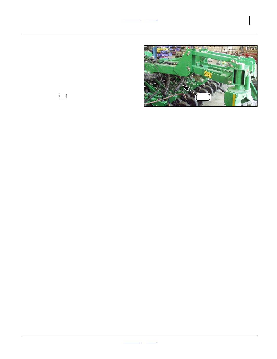
Refer to Figure 119
274. Route hoses
inside of implement center frame,
using letters on hose guides for placement. Exit
hoses below frame, ahead of lift-assist link. Primary
hoses are connected to towers at step 316 on
page 79.
Null4:
Null4:
Figure 119
Route Primary Hoses
Q0057
308
308
This manual is related to the following products: