Position cart frame, Clear hopper(s), Check hopper straps – Great Plains NTA2007HD Predelivery Manual User Manual
Page 16
12
Great Plains Manufacturing, Inc.
NTA607HD
166-283Q
02/09/2011
Position Cart Frame
Refer to Figure 12
(depicting factory stands not shipped with the drill)
Note: This operation usually requires two lifters. Lowered
from single lift, the cart tends to settle on its rear
end, or inverted.
11. Use the second lifter
to pull the rear of the cart
frame away from the first lifter.
12. When the frame is near level, position two stands
to support the front of the cart. Keep the stands
clear of the tongue flanges. Secure the stands to
the cart frame if possible.
13. Lower the cart frame onto the stands at front, and
onto the transport wheel hubs at rear.
14. Remove the shipping eyebolts at the front lift points.
These eyebolts are not re-used.
Null4:
Clear Hopper(s)
Refer to Figure 13
15. Open a hopper lid(s). Remove the strainer(s)
.
16. Remove and save all materials shipped inside hop-
pers.
Doing this at this time reduces the weight of the
hopper frame, and provides easier access, as the
hopper lids are closer to the ground.
17. Return strainer(s) to hopper(s). Secure lid(s).
Null4:
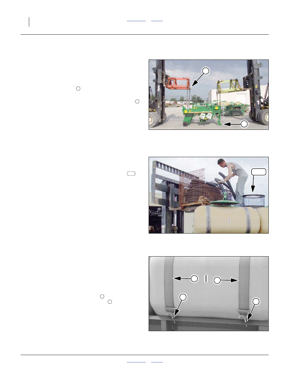
Check Hopper Straps
Refer to Figure 14
Hoppers may have seated or straps may have stretched
in transit.
18. Check tension before dismount and installation.
Tighten nuts on tensioning bolts
until straps can-
not slide side to side on hopper face
, then tighten
nuts two additional turns.
Null4:
Figure 12
Spot Cart Frame
Q0007
5
6
5
6
Null4:
Figure 13
Empty Hopper(s)
Q0016
135
135
Null4:
Figure 14
Hopper Strap Tensioning
31412
1
1
2
2
1
2