Connect lift assist link, Install upper rear arms, Connect lift assist link install upper rear arms – Great Plains NTA2007HD Predelivery Manual User Manual
Page 41
Great Plains Manufacturing, Inc.
Implement Assembly
37
02/09/2011
166-283Q
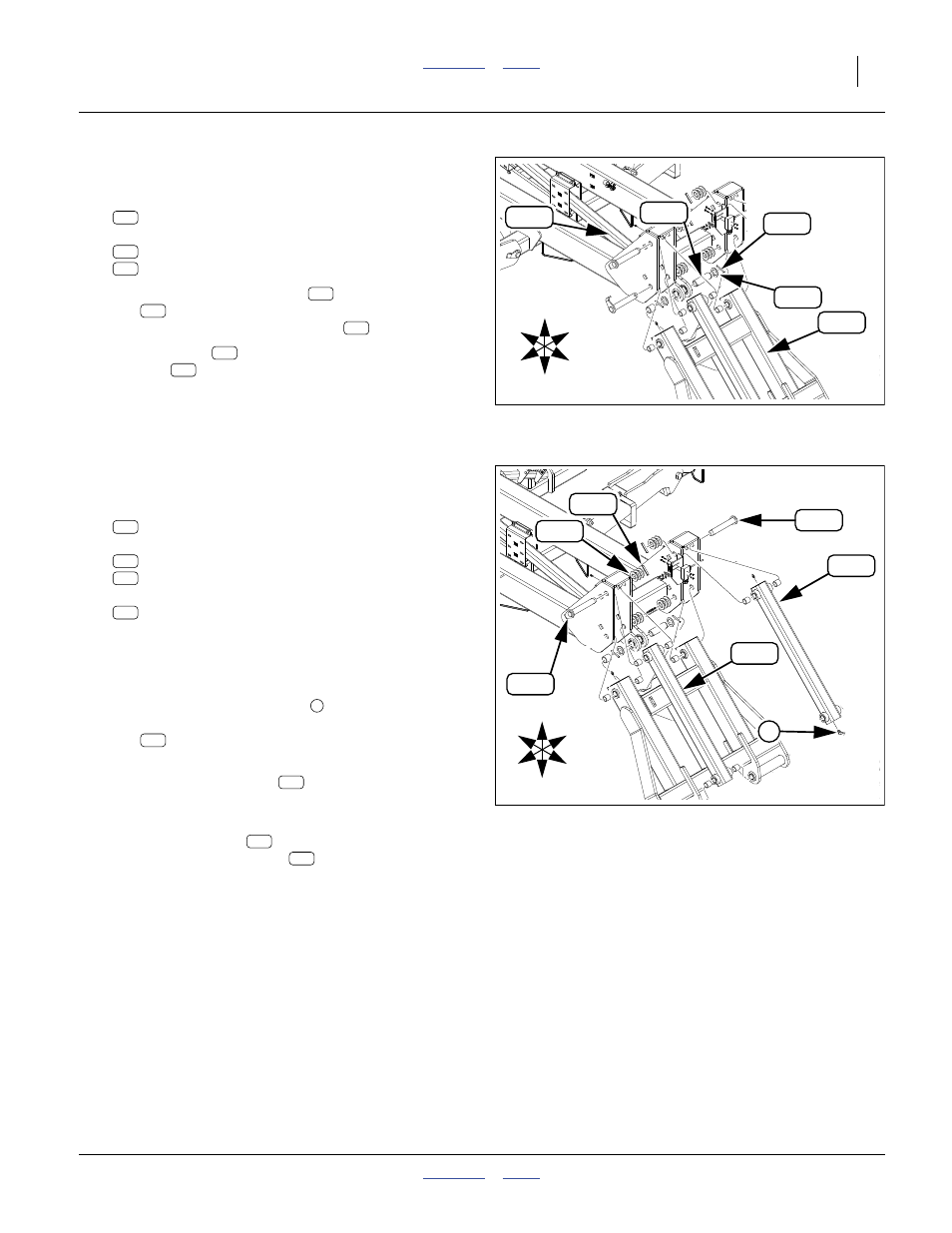
Connect Lift Assist Link
Refer to Figure 57
128. Select one:
160-781D PIN 1 1/2 X 4 USABLE 1045
and two sets:
804-063C WASHER MACH 2.25 X 1.50 X 10GA
805-117C PIN ROLL 1/4 X 2 1/2 PLT
129. Adjust angle of rear pull link
and lift assist
link
until bushing centers of pull link lug and link
clevis are in alignment. Insert pin
.
130. Add a washer
to each end of pin. Secure with
roll pins
.
Null4:
Install Upper Rear Arms
Refer to Figure 58
131. Select two:
160-314H REAR PARALLEL LIFT LINK WELDMT
and two:
160-201H WING PIVOT PIN WELDMENT
805-255C PIN ROLL 3/8 X 2 1/2 PLT
and six:
804-039C WASHER FLAT 1 1/4 SAE PLT
Note that one end (the front) of each link has a
straight grease zerk, and the other (rear) end has a
right angle zerk.
132. With the angled grease zerk
to the rear, zerk fac-
ing up, align the bushings of the front end of the
link
with the upper rear holes in the center sec-
tion plates.
133. From outside, insert pin
. Fully seat the break in
the pivot pin cap in the square hole of the outside
center section plate.
134. Add three washers
.
Secure pins with roll pins
.
Null4:
Null4:
Figure 57
Connect Lift Assist Linkage
31259
U
D
L
R
B
F
242
111
128
238
118
128
238
242
111
118
128
239
242
Null4:
Figure 58
Upper Rear Arms
31259
U
D
L
R
B
F
109
232
108
247
108
1
109
109
108
247
232
109
108
232
247