Install contact drive, Install drive assembly – Great Plains NTA2007HD Predelivery Manual User Manual
Page 27
Great Plains Manufacturing, Inc.
Cart Assembly
23
02/09/2011
166-283Q
Install Contact Drive
Install Drive Assembly
Refer to Figure 30
66. Locate the contact drive assembly:
166-323K NTA607HD CONTACT WHEEL ASSY
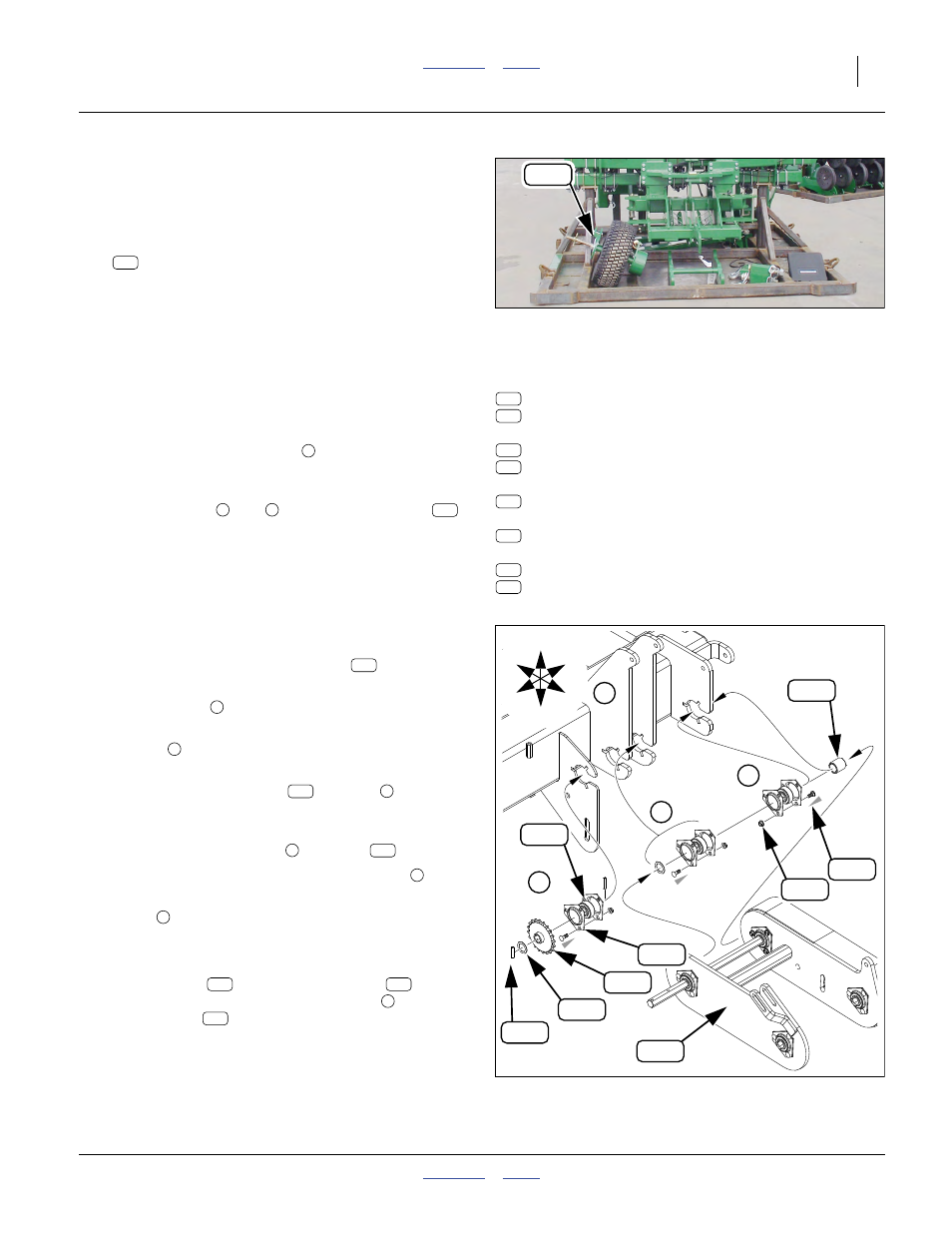
Refer to Figure 31 (depicting the drive assembly without the
tire and wheel for clarity)
67. Inspect any bearings, flangettes, fastener, spacers,
spacer washer and pins installed on the output
shaft. Installation requires
If some of these components are not on the shaft,
they may be on the cart frame, or in a carton.
68. If pre-installed on the shaft and/or frame, remove
and save component group
. Remove and save all
fasteners.
69. If not pre-installed on the shaft, loosely install com-
ponent groups
and
(including the spacer
,
but without the fasteners). This may require some
disassembly of the contact drive. Refer to the Parts
manual for component ordering inside the drive
housing.
70. Using a hoist, guide the contact drive output shaft
into the frame’s bearing plate cutouts. Note the fol-
lowing before commencing insertion:
71. Loosely secure flangette
with nuts
.
72. Insert bolts and loosely secure with nuts at
.
73. Loosely install bearing and flangette of component
group
at left-most plate.
74. Tighten nuts at flangettes. Turn wheel periodically to
assure bearing alignment.
75. Add sprocket
and machine washer
to left
end of shaft. Secure component group
to shaft
with roll pins
.
Leave the hoist attached to the drive for the next steps.
Null4:
• All loose (frame plate) flangettes
mount on
the left side of frame plates.
• Frame plate
does not take a flangette.
• Bolt head orientation is critical, particularly for
group
, where clearances are tight. See gray
arrow heads for insertion direction.
• Pre-insert just the bolts
at group
, to ease
assembly.
Null4:
Null4:
Shaft Components Required:
one [1] each:
266-194D CONTACT WHEEL SPACER TUBE
808-305C SPKT 50C20 X 7/8 HEX BORE
two [2] each:
804-061C WASHER MACH 1.50 X 1.00 X 18GA
805-208C PIN, ROLL 1/4 X 1 1/4 LONG
three [3] each:
822-195C BRG INS 7/8HEXX2.04OD SPH
six [6] each:
822-175C FLANGETTE 52 3-BOLT PLT
and nine [9] sets of:
802-282C RHSNB 5/16-18X1 GR5
803-177C NUT HEX FLG TP LK 5/16-18ZNYCR
Figure 30
Drive Assembly on Center Rack
Q0003
146
254
234
246
285
284
195
217
131
131
D
B
A
146
Null4:
Figure 31
Contact Drive Shaft Ordering
Q0020
D
{
B
A
C
146
217
195
131
285
284
254
234
246
U
D
L
R
B
F
284
C
B
195
B
B
217
A
D
254
234
D
246