Connect sensor leads, Connect leads, Connect – Great Plains NTA2007HD Predelivery Manual User Manual
Page 89
Great Plains Manufacturing, Inc.
Implement Assembly
85
02/09/2011
166-283Q
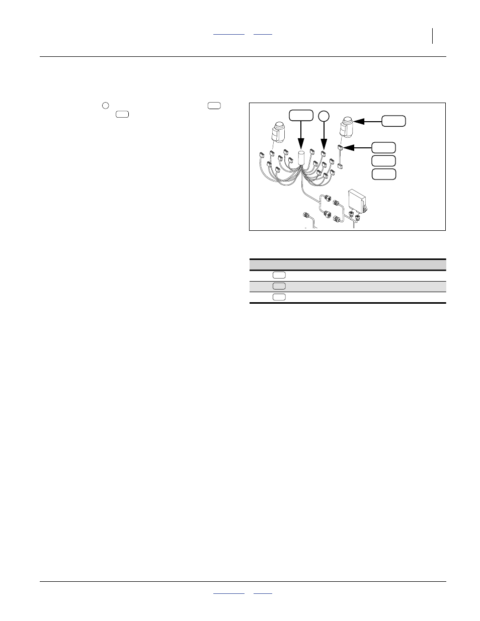
Connect Sensor Leads
Refer to Figure 153
The sensor leads
connect the row harnesses
to
the blockage sensors
. Each numbered lead con-
nects to a specific drop-numbered sensor. Lead/drop
assignments are specific to row spacing and tower
count.
The lead cables are numbered from “1” to “12” (or “16”).
This corresponds to “WSMBx-01” to “WSMBx-16” in the
Appendix tables.
Note: The sensor lead number, in most cases,
is NOT the row number and
is NOT the drop number.
Rely on the Appendix tables beginning on page 96
for matching harness leads
Connectors on row harness leads are normally capped
by a plug as delivered. Some row configurations do not
use all leads from a harness. Leave the plugs in the con-
nectors for unused leads.
Some row configurations (e.g. 40-row double-shoot),
require connections to a WSMB and row harness not at
the current tower. Sensor harness extensions are pro-
vided for this. The Appendix tables indicate the rows and
sensor lead extensions required. Extension identification
is shown in the table at right.
Connect Leads
346. Find the table(s) for the present implement. There
are 6 sets of tables, per row spacing/count, and
whether single-shoot/-hopper or double-shoot.
347. At Tower A, Lead 1, connect the lead to the block-
age sensor bearing the “Drop No.” shown in the
Appendix table.
For Tower A, this happens to be Lead 1 and Drop 1
in all cases, but this Lead=Drop number correspon-
dent diverges at subsequent rows, sometimes as
early as Lead 9.
348. Continue at Lead 2 for the current row harness, and
connect all used leads per the table. Watch for two
additional matters in the tables:
a. Some leads may be unused (leave dust plugs in).
b. Some leads have an entry in the “Lead Ext.” col-
umn (see step 350) for this).
349. Move to the nearest unconnected tower, which is
Tower B for single, and Tower E for double-shoot.
Null4:
Null4:
Figure 153
Sensor Leads
Q0081
Ext. Extension Part
+3
459680920 EXT. HARNESS 3’, FAN RPM
+10
457901815 DJ HARNESS 10 FT EXT 3 PIN WP
+15
459680922 EXT. HARNESS 15’ FAN RPM
154
152
155
159
152
160
154
155
1
1
160
159