Install wing towers, Install wing base towers, Fb r l – Great Plains NTA2007HD Predelivery Manual User Manual
Page 79
Great Plains Manufacturing, Inc.
Implement Assembly
75
02/09/2011
166-283Q
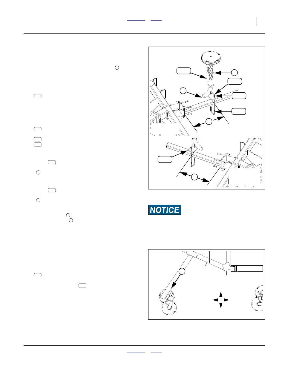
Install Wing Towers
Install Wing Base Towers
Refer to Figure 134
Note: It may be necessary to loosen U-bolts
and raise
the position of the tower to avoid interference.
Leave the U-bolts only snug for adjustment at
step 299.
297. Select two of either:
168-433K NTA607HD 10 OUTLET TOWER ASY
168-435K NTA607HD 8 OUTLET TOWER ASY
If the towers already have letter labels, choose
towers A and D.
298. Select two sets:
806-206C U-BOLT 1/2-13X4 1/32X4
and four sets:
804-015C WASHER LOCK SPRING 1/2 PLT
803-020C NUT HEX 1/2-13 PLT
Install the LEFT wing tower (A) with the following
distance between the forward edge of the
mount
and the front outside end of the weld-
ment tube:
44.5cm (17
1
⁄
2
in)
Install the RIGHT wing tower (B) with the following
distance between the forward edge of the
mount
and the front outside end of the weld-
ment tube:
101.0cm (39
3
⁄
4
in)
Refer to Figure 135 (depicting a view from beneath the drill)
299. Loosen U-bolts
. Adjust vertical position of towers
so that the inlets
are about 1cm (
3
⁄
8
in) above
mount tubes. Leave U-bolts only snug for further
adjustment at a later step.
Refer to Figure 131 on page 73
If the towers already have letter labels, skip step 300 and
step 301.
300. Clean dry the tower tubes just above the inlet bend.
301. Select the:
848-553C DECAL BIN-PRIMARY LINE SHEET
From the decal sheet
, select letters A and B.
Apply letter decal A to the left-wing base tower tube.
Apply letter decal B to the right-wing base tower
tube.
Null4:
Null4:
Null4:
Null4:
Equipment Damage Risk:
Tower placement is different for left and right wing, to allow
tower-to-tower clearance during folding. If not placed at the
correct locations, they may collide during the first fold and can
be seriously damaged.
Figure 134
Install Wing Base Tower
31271
7
6
Null4:
(A)
LEFT WING
136
252
225
206
8
Null4:
(B)
RIGHT WING
(Not to Scale)
136
139
252
225
206
136
136
Null4:
Figure 135
Wing Tower Inlet
Q0060
F
B
R
L
302
302