Install hoses, Cut hose, Figure 150 on – Great Plains NTA2007HD Predelivery Manual User Manual
Page 87
Great Plains Manufacturing, Inc.
Implement Assembly
83
02/09/2011
166-283Q
Install Hoses
Secondary hoses run from tower exit ports, through
blockage sensors, and to row drops (seed or fertilizer).
Hose lengths are specific to tower, row and function.
Hoses are not identified by number until the blockage
sensors are installed, so it is recommended that each
hose be completely installed before moving to the next
hose.
Cut Hose
Start with Tower A, then complete towers B-D, and if dou-
ble-shoot; E-H.
At each tower, begin hose installation at any Drop No.
337. Select a coil of:
990-080R HOSE 3/8 ID 150PSI EPDM
338. For the chosen port on the present tower, consult
the Appendix (page 97 through page 102) for the
port mapping for the implement row spacing, distri-
bution option (single or double-shoot) and tower set
(seed or fertilizer). Find the “Hose Length” for that
“Drop No.” Cut a length of hose as specified.
Take care to cut ends square.
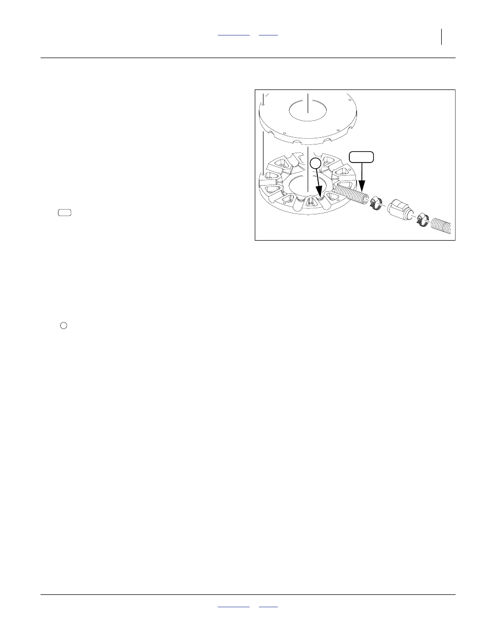
339. Insert one end of the hose into the present port. The
correct seating depth to the constriction is:
5.8cm (2.3in)
If seated beyond this depth, the turret’s divider sec-
tions may have a gap at closeout, leaking air, upset-
ting seed flow balance or causing blockages.
If the hose seated with insufficient depth, the hose
may fall out in use, or seed may collect at the hose
inlet, or seed flow balance may be upset.
340. Insert the other end of the hose in the rubber boot at
the same numbered drop on an opener.
341. When all the hoses for a single tower are inserted,
tighten the cap bolts for the turret. Check that the
divider halves are sealed together at their mating
faces. Check that all hoses are snug at ports.
Null4:
Figure 150
Hose at Tower Divider
31272
307
5
307