Assemble lock cylinder valve, Install lock cylinder valve – Great Plains NTA2007HD Predelivery Manual User Manual
Page 51
Great Plains Manufacturing, Inc.
Implement Assembly
47
02/09/2011
166-283Q
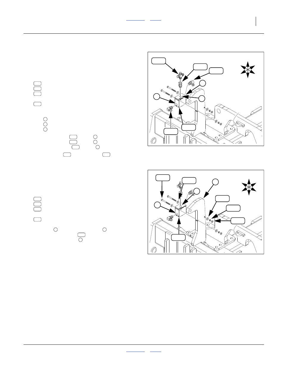
Assemble Lock Cylinder Valve
If the fittings are pre-assembled on the valve, review the
Figure for Port ID and orientation, then skip to step 181.
See page 95 for JIC and ORB torque.
Refer to Figure 77
178. Select one each:
810-428C VALVE PO CHECK 4:1 W/9/16FORB
811-627C AD 9/16MORB 9/16FJIC
811-581C CR 9/16MJIC
and two:
811-065C EL 9/16MJIC 9/16MORB
Orientation:
Port
: front
Port
: rear
Port
: top
179. Install one elbow
at port
, JIC end to left.
Install one elbow
at port
, JIC end down.
Install the adaptor
at port
.
180. Add the cross
to the adaptor
, with side
ports facing front and rear.
Null4:
Install Lock Cylinder Valve
Note: This installation places the label side of the POC
valve against the lug.
Refer to Figure 78
181. Select two sets:
802-804C HHCS 1/4-20X2 3/4 GR8 PLT
804-006C WASHER LOCK SPRING 1/4 PLT
803-006C NUT HEX 1/4-20 PLT
and four:
804-075C WASHER FLAT 1/4 USS PLT
With port
to the front, and port
up, mount the
POC valve assembly
on the right side of the
lock cylinder base lug
. Bring nuts only to snug, as
you may prefer to remove the valve later for hose
installation.
Null4:
Null4:
Figure 77
Lock Cylinder Valve Assembly
Q0054
260
262
273
275
262
1
2
3
U
D
F
B
L
R
260
275
273
262
262
262
275
273
275
Null4:
Figure 78
Install Lock Cylinder Valve
Q0054
260
200
235
203
U
D
F
B
L
R
220
235
4
200
220
203
235
260