Seed/fertilizer hose port maps, Primary hose routing (all spacings), Primary hose, double-shoot – Great Plains NTA2007HD Predelivery Manual User Manual
Page 100: Primary hose, dual-hopper, single-shoot, Primary hose, single-hopper
96
Great Plains Manufacturing, Inc.
NTA607HD
166-283Q
02/09/2011
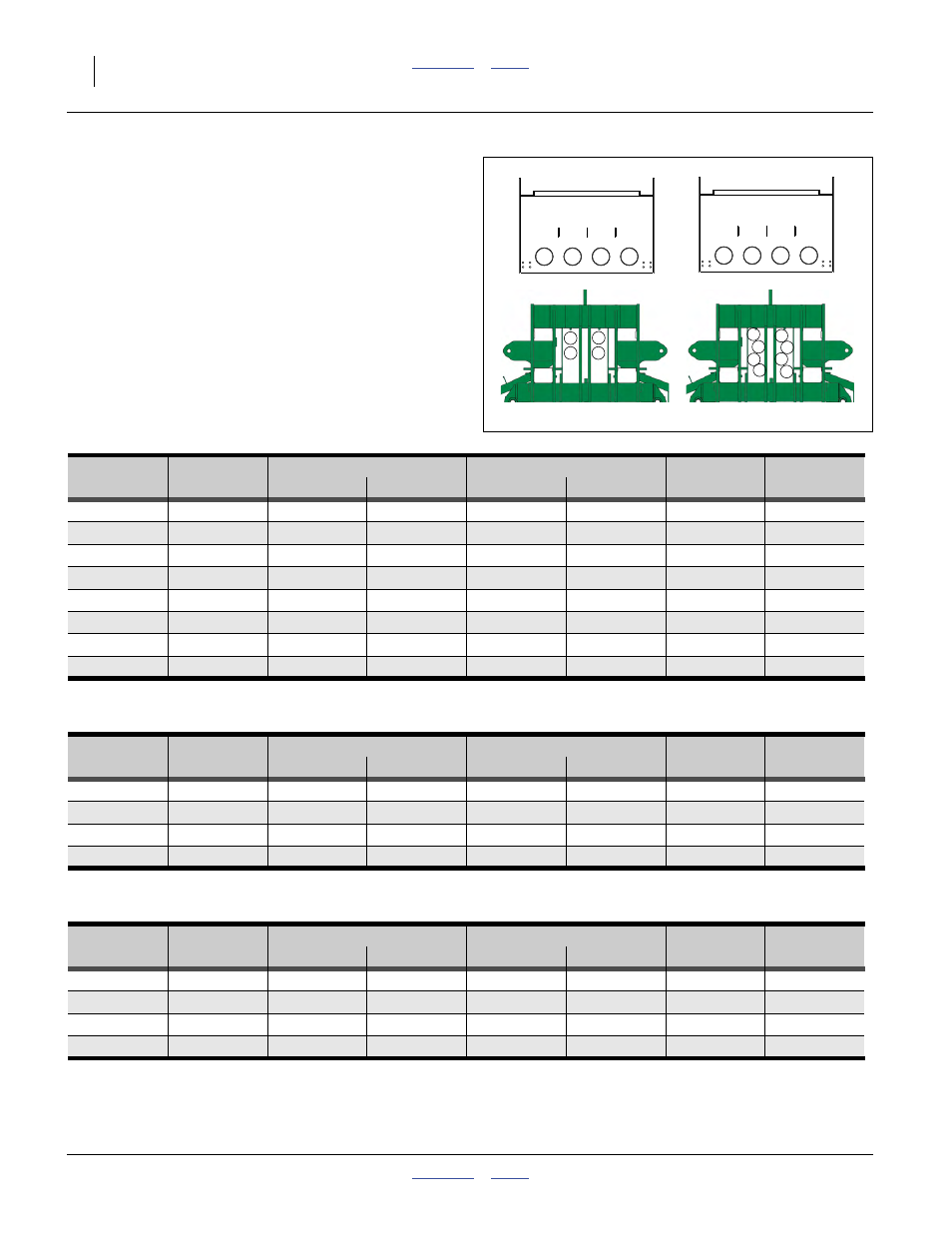
Seed/Fertilizer Hose Port Maps
Primary Hose Routing (all spacings)
Primary Hose Routing (from meter outlet or Y-tube to
towers, varies by hopper configurations, but is same for
all row spacings).
Illustrations at right show meter outlets (top) and portals
at front of implement center frame.
Left/Right is facing in the direction of drill travel (forward).
Note: Hoses G and F will cross each other under the rear
of the implement frame, in order to reach their re-
spective towers. This is normal.
Primary Hose, Double-Shoot
Null4.aac:
Primary Hose, Dual-Hopper, Single-Shoot
Null4.aac:
Primary Hose, Single-Hopper
Null4.aac:
B
A
C
D
G
B
A
E
C
F
H
D
I
II
1
1
2
3
4
2
3
4
B
D
A
C
G
H
E
F
Single-Shoot
Double-Shoot
Hopper
Meter
Primary Hose Length*
Link Routing
Implement
Distribution
Number
Outlet
Metric
Inches
Portal
Position
Section
Tower
I
1 (B)
437 cm
172 in.
Left
Upper-R
Center
B
I
2 (A)
602 cm
237 in.
Left
Lower-L
Left
A
I
3 (D)
709 cm
279 in.
Right
Lower-R
Right
D
I
4 (C)
437 cm
172 in.
Right
Upper-L
Center
C
II
1 (G)
528 cm
208 in.
Left
Upper-L
Center
G
II
2 (E)
602 cm
237 in.
Left
Lower-R
Left
E
II
3 (H)
709 cm
279 in.
Right
Lower-L
Right
H
II
4 (F)
528 cm
208 in.
Right
Upper-R
Center
F
* Hose length may be shortened a few cm/in after checking slack and clearances during lift and fold.
Hopper
Meter
Primary Hose Length*
Link Routing
Implement
Distribution
Number
Outlet
Metric
Inches
Portal
Position
Section
Tower
I + II
1 (B)
376 cm
148 in.
Left
Upper
Center
B
I + II
2 (A)
541 cm
213 in.
Left
Lower
Left
A
I + II
3 (D)
648 cm
255 in.
Right
Lower
Right
D
I + II
4 (C)
376 cm
148 in.
Right
Upper
Center
C
* Hose length may be shortened a few cm/in after checking slack and clearances during lift and fold.
Hopper
Meter
Primary Hose Length*
Link Routing
Implement
Distribution
Number
Outlet
Metric
Inches
Portal
Position
Section
Tower
I
1 (B)
406 cm
160 in.
Left
Upper
Center
B
I
2 (A)
572 cm
225 in.
Left
Lower
Left
A
I
3 (D)
678 cm
267 in.
Right
Lower
Right
D
I
4 (C)
406 cm
160 in.
Right
Upper
Center
C
* Hose length may be shortened a few cm/in after checking slack and clearances during lift and fold.