Status indicators – Rockwell Automation 2097-Vxxx Kinetix 350 Single-axis EtherNet/IP Servo Drive User Manual User Manual
Page 79
Rockwell Automation Publication 2097-UM002C-EN-P - December 2013
79
Configure and Start Up the Kinetix 350 Drive System Chapter 5
Status Indicators
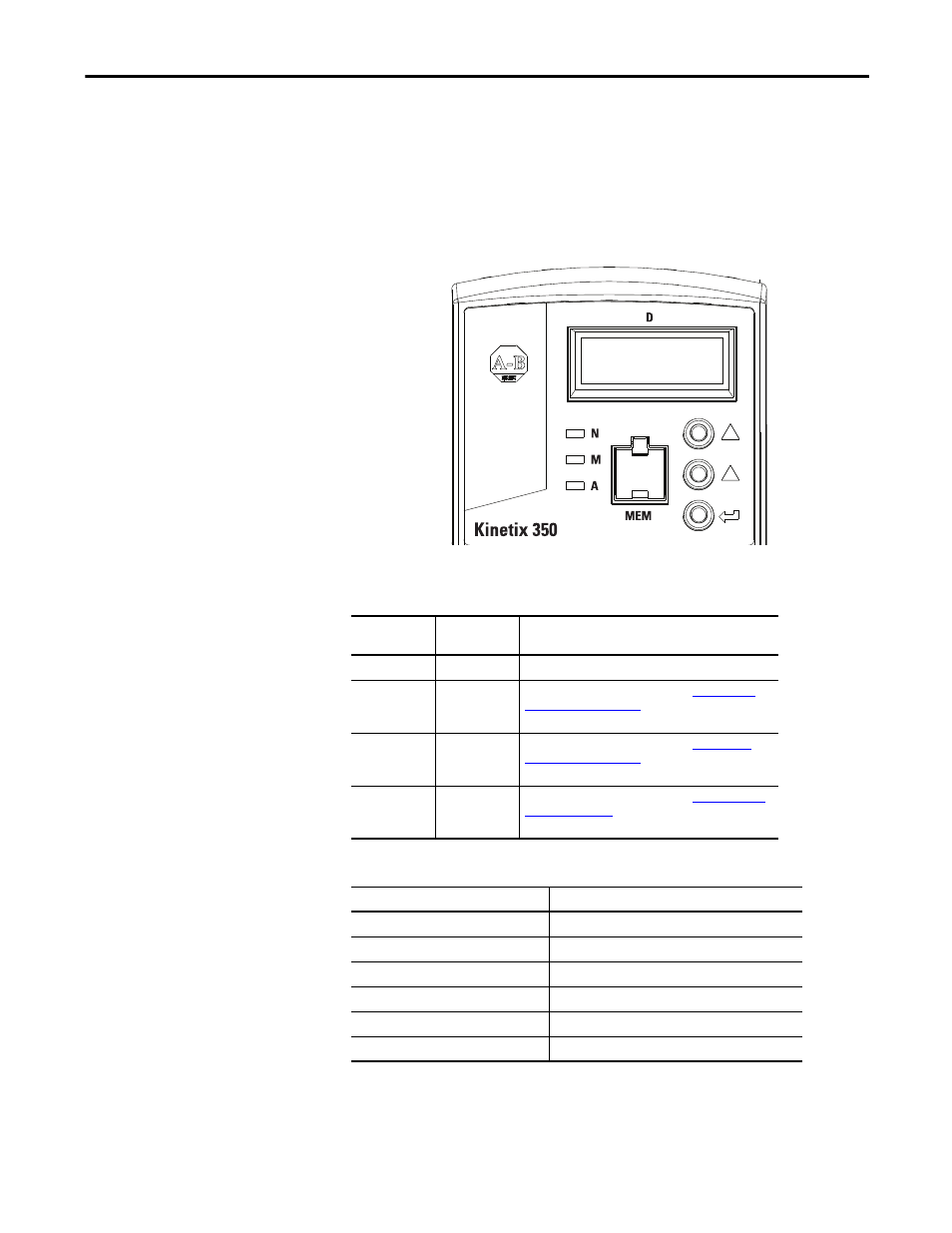
The Kinetix 350 drive has four status indicators and a four-digit display on the
top front panel as shown below. These status indicators and the display are used
to monitor the system status, activity, and troubleshoot faults.
Figure 45 - Front Panel Display
Table 36 - Module State Status Indicator
Table 35 - Status Indicators
Status
Indicator
Function
Description
D
Data entry
Yellow status indicator flashes when changing.
N
Network state
Indicates the state of the Network. See
. The bicolored status indicator
shows red, green, or amber.
M
Module state
Indicates the state of the Network. See
. The bicolored status indicator
shows red, green, or amber.
A
Axis state
Indicates the state of the Network. See
. The bicolored status indicator shows
red, green, or amber.
Status Indicator
State
Off
Power off
Flash red/green
Drive self-testing
Flashing green
Standby
Solid green
Operational
Flashing red
Major recoverable fault
Solid red
Major unrecoverable fault