Kinetix 350 drive/actuator wiring examples – Rockwell Automation 2097-Vxxx Kinetix 350 Single-axis EtherNet/IP Servo Drive User Manual User Manual
Page 136
136
Rockwell Automation Publication 2097-UM002C-EN-P - December 2013
Appendix A Interconnect Diagrams
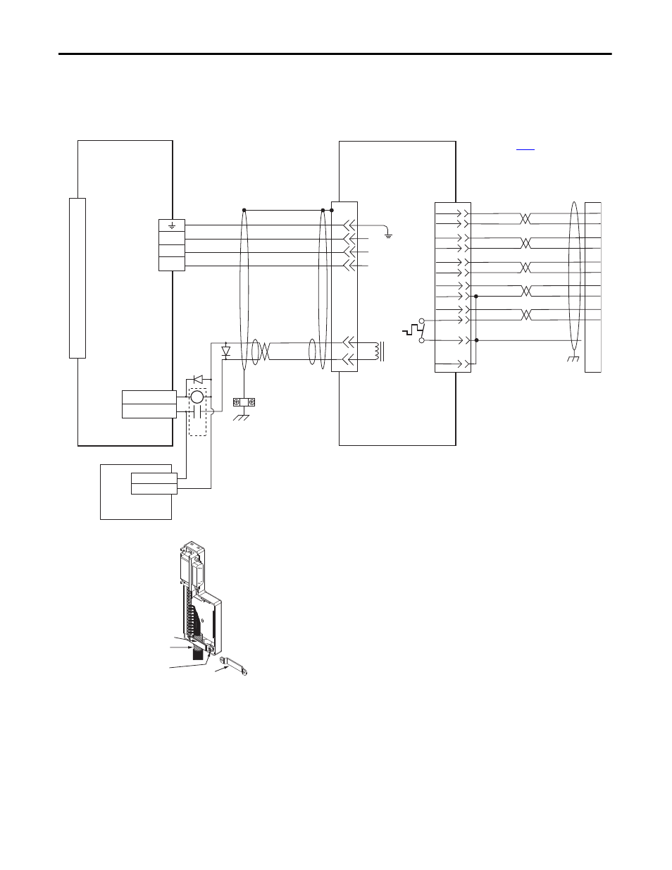
Kinetix 350 Drive/Actuator
Wiring Examples
These wiring diagrams apply to Kinetix 350 drives with compatible linear
actuators.
Figure 59 - Kinetix 350 Drive with MP-Series (Bulletin MPAS-A/B) Linear Stages
D
C
B
A
BR+
BR-
F
G
W
V
U
SIN+
SIN-
COS+
COS-
DATA+
DATA-
+5VDC
ECOM
GREEN
WHT/GREEN
GRAY
WHT/GRAY
BLACK
WHT/BLACK
RED
WHT/RED
3
4
5
6
1
2
9
10
1
2
3
4
5
10
14
6
14
12
+9VDC
TS+
ORANGE
WHT/ORANGE
11
13
7
11
Green/Yellow
Blue
Black
Brown
Black
White
GND
Shield
W
V
U
TS-
COM
BLUE
1
2
3
4
5
6
7
8
9
10
11
12
13
14
15
CR1
MTR_BRAKE -
MTR_BRAKE +
44
43
24V DC
24V DC COM
MPAS-A/Bxxxxx-VxxSxA
Ballscrew Linear Stages
with
High Resolution Feedback
Motor Brake
Three-phase
Motor Power
Motor
Feedback
2090-K2CK-D15M
Connector Kit
I/O (IOD)
Connector
Note 4
Motor Power
(MP) Connector
2097-V3xPRx-LM
Kinetix 350 Drives
Motor Feedback
(MF) Connector
User Supplied
24V DC
Turn clamp over to hold
small cables secure.
Exposed shield secured
under clamp.
Clamp Screws (2)
Clamp
Refer to table on
for note information.
2090-XXNPMF-xxSxx (standard)
or 2090-CPBM4DF-xxAFxx
(continuous-flex)
Motor Power Cable
Use 2090-CPWM4DF-xxAFxx
cable for continuous-flex non-brake
applications.
Refer to low profile connector
illustration (lower left)
for proper grounding technique.
2090-XXNFMF-Sxx (standard) or
2090-CFBM4DF-CDAFxx (continuous-flex)
(flying-lead) Feedback Cable
Notes 9, 11
Cable Shield
Clamp
Note 8
Thermostat
Low Profile Connector
(2090-K2CK-D15M shown)
Grounding Technique for
Feedback Cable Shield