Control signal specifications, Digital inputs – Rockwell Automation 2097-Vxxx Kinetix 350 Single-axis EtherNet/IP Servo Drive User Manual User Manual
Page 41
Rockwell Automation Publication 2097-UM002C-EN-P - December 2013
41
Kinetix 350 Drive Connector Data Chapter 3
Control Signal Specifications
This section provides a description of the Kinetix 350 drive I/O (IOD),
communication, shunt resistor and DC bus (BC), and back-up power (BP)
connectors.
Digital Inputs
Five fixed inputs are available for the machine interface on the Kinetic 350 drive.
The five digital inputs (IOD-27…IOD-30 and IOD-39) have fixed pin
assignments.
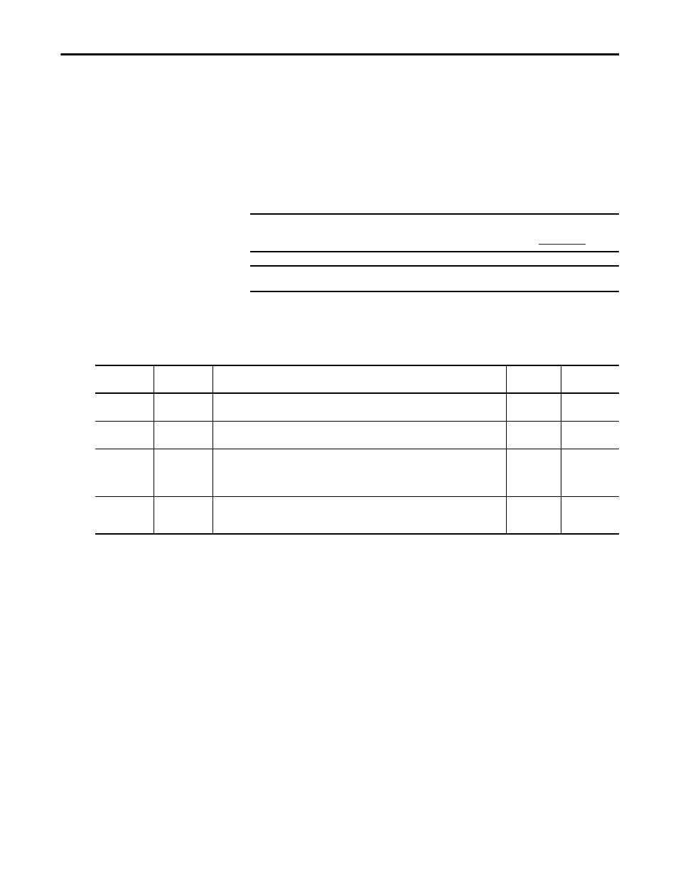
Table 12 - Understanding Digital Inputs
IMPORTANT
To improve registration input EMC performance, refer to the System Design for
Control of Electrical Noise Reference Manual, publication
IMPORTANT
Over-travel limit input devices must be normally closed.
IOD Pin
Signal
Description
Capture
Time
Edge/Level
Sensitive
IOD-29
ENABLE
Optically isolated, single-ended active high signal. Current loading is nominally 9 mA. A 24V
DC input is applied to this terminal to enable the axis.
0.5 ms
Level
IOD-30
HOME
Optically isolated, single-ended active high signal. Current loading is nominally 9 mA. Home
switch (normally open contact) inputs axis require 24V DC (nominal).
0.5 ms
Edge
IOD-39
REG
Fast registration inputs are required to inform the motor interface to capture the positional
information with less than 5 μs uncertainty. Optically isolated, single-ended active high
signal. Current loading is nominally 9 mA. A 24V DC input is applied to this terminal to enable
axis.
5 μs
Edge
IOD-27
IOD-28
NEG_OT
POS_OT
Overtravel detection is available as an optically isolated, single-ended active high signal.
Current loading is nominally 9 mA per input. The positive/negative limit switch (normally
closed contact) inputs for axis require 24V DC (nominal).
1 ms
Level