Shunt resistor connections, Ethernet cable connections – Rockwell Automation 2097-Vxxx Kinetix 350 Single-axis EtherNet/IP Servo Drive User Manual User Manual
Page 75
Rockwell Automation Publication 2097-UM002C-EN-P - December 2013
75
Connect the Kinetix 350 Drive System Chapter 4
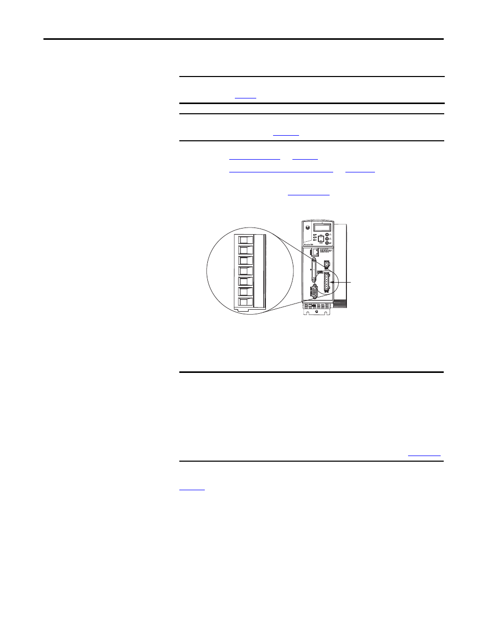
Shunt Resistor Connections
Follow these guidelines when wiring your 2097-R
x shunt resistor.
• Refer to
for noise zone considerations.
• Refer to
.
• Refer to the installation instructions provided with your Bulletin 2097
shunt resistor, publication
Figure 42 - Shunt/DC Bus (BC) Connector
Ethernet Cable Connections
This guideline assumes you have your Logix5000 Ethernet/IP module and
Kinetix 350 drive mounted and ready to connect the network cables.
The EtherNet/IP network is connected by using the Port 1 connector. Refer to
to locate the Ethernet connector on your Kinetix 350 drive. Refer to the
figure below to locate the connector on your Logix5000 communication module.
Shielded Ethernet cable is available in lengths up to 78 m (256 ft). However, the
total length of Ethernet cable connecting drive-to-drive, drive-to-controller, or
drive-to-switch must not exceed 100 m (328 ft).
IMPORTANT
When tightening screws to secure the wires, refer to the tables beginning on
for torque values.
IMPORTANT
To improve system performance, run wires and cables in the wireways as
established in
+
+
SH
-
-
Kinetix 350 Drive
Front view is shown.
Shunt/DC Bus
(BC) Connector
IMPORTANT
ENET-TD001
.