Shunt resistor wiring example – Rockwell Automation 2097-Vxxx Kinetix 350 Single-axis EtherNet/IP Servo Drive User Manual User Manual
Page 133
Rockwell Automation Publication 2097-UM002C-EN-P - December 2013
133
Interconnect Diagrams Appendix A
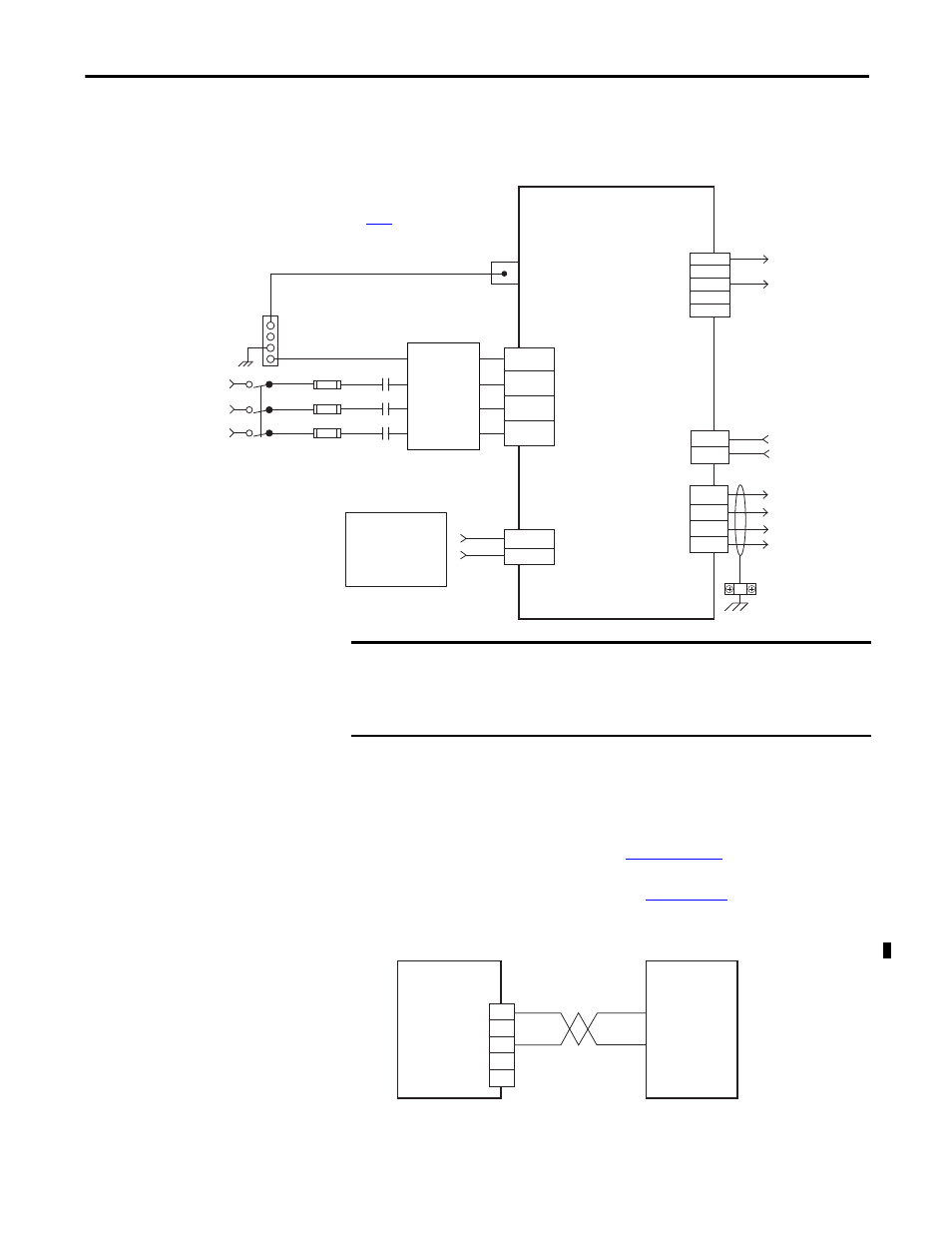
In this example, three-phase 240V AC is applied to 2097-V33PR
x-LM drives
and 480V AC is applied to 2097-V34PR
x-LM drives.
Figure 55 - Kinetix 350 Drive (240/480V three-phase input power)
Shunt Resistor Wiring Example
Refer to the Kinetix 350 Drive Power Specifications in Kinetix Servo Drives
Specifications Technical Data, publication
for the Bulletin 2097-
R
x shunt resistors available for the Kinetix 350 drives. Refer to the Shunt
Resistor Installation Instructions, publication
, for additional
installation information.
Figure 56 - Shunt Resistor Wiring Example
PE
L1
L2
L3
+24V DC
-24V DC
+
+
SH
-
-
L1
L2
L3
U
V
W
PE
EN
ACOM
29
26
Three-phase AC Input
240/480V rms AC, 50/60 Hz
Ground Stud
Mains
Three-phase Input
(IPD) Connector
Fuse Disconnect
or Circuit Breakers
Input Fusing *
M1 *
Notes 5, 7
Three-phase
Motor Power
Connections
Note 9
Motor Power
(MP) Connector
Cable Shield
Clamp
Note 8
I/O (IOD)
Connector
Shunt
Resistor
Connections
2097-V33PRx-LM and
2097-V34PRx-LM
Kinetix 350 Drive
* Indicates User Supplied Component
Refer to table on
page 130
for note information.
AC Line Filter
(optional)
Note 3
Use discrete logic or PLC to
control ENABLE to drive
User-supplied
+24V DC
Back-up Power
(BP) Connector
Shunt Resistor
and DC Bus
(BC) Connector
Bonded Cabinet
Ground Bus *
IMPORTANT
For the 480V Kinetix 350 drives to meet ISO 13849-1 (PLd) spacing
requirements, each phase voltage to ground must be less than or equal to 300V
AC rms. This means that the power system must use center grounded wye
secondary configuration for 400/480V AC mains.
+
+
SH
-
-
2097-V3xPRx-LM
Kinetix 350 Drive
2097-Rx
Shunt
Resistor
Shunt/DC Bus
(BC) Connector
(1)
(1) This connector is for the shunt resistor, not the motor brake.