Rockwell Automation 2097-Vxxx Kinetix 350 Single-axis EtherNet/IP Servo Drive User Manual User Manual
Page 68
68
Rockwell Automation Publication 2097-UM002C-EN-P - December 2013
Chapter 4 Connect the Kinetix 350 Drive System
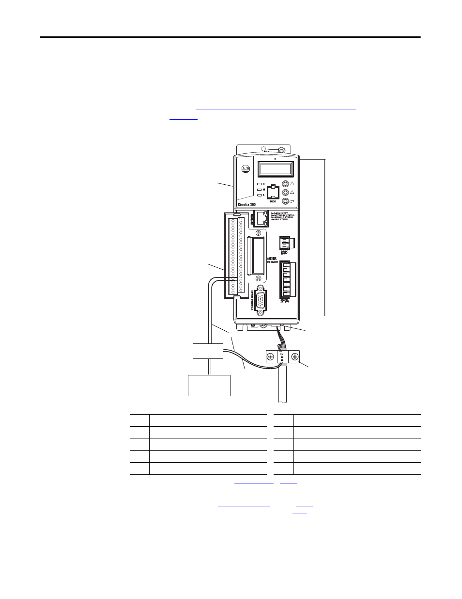
This diagram shows an example of wiring with three-phase power wires and brake
wires. The brake wires have a shield braid (shown below as gray) that folds back
under the cable clamp before the conductors are attached to the motor brake
circuit. Thermal switch wires are included in the feedback cable.
Kinetix 350 Drive/Rotary Motor Wiring Examples
beginning on
for interconnect diagrams.
Figure 37 - Motor Power Terminations (three-phase and brake wires)
Cable shield and lead preparation is provided with most Allen-Bradley cable
assemblies. Follow these guidelines if your motor power cable shield and wires
require preparation.
1
2
3
To Motor
6
7
5
8
4
Item
Description
Item
Description
1
(1)
24V power supply
5
I/O (IOD) connector
(2)
2
(1)
Relay and diode assembly
(3)
6
2097-V3xPRx-LM Kinetix 350 drive
3
Minimize unshielded wires in brake circuit
7
Motor power (MP) connector
4
MP-Series cable brake wires
8
Cable clamp
(4)
(1) User supplied. Size as required by motor brake, See
(2) Pin 43 and 44 are configured as MTR_ BRAKE+ and MTR_BRAKE- Common respectively. Wire the output as sourcing and set brake engage and disengage
times for motor selected. Motor brake is active on enable.
(3) Diode 1N4004 rated 1.0 A @ 400V DC. See
(4) Exposed shield under clamp and place within 50…75 mm (2…3 in.) of drive, see
for details.