Rockwell Automation 2097-Vxxx Kinetix 350 Single-axis EtherNet/IP Servo Drive User Manual User Manual
Page 135
Rockwell Automation Publication 2097-UM002C-EN-P - December 2013
135
Interconnect Diagrams Appendix A
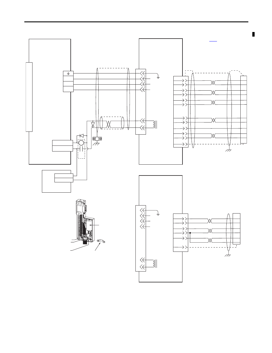
Figure 58 - Kinetix 350 Drive with TL-Series (TLY-A) Motors
5
3
2
1
BR+
BR-
7
9
W
V
U
GND
0
1
2
3
4
5
6
7
8
9
10
11
12
13
14
15
Green/Yellow
Blue
Black
Brown
Black
White
W
V
U
AM+
AM-
BM+
BM-
IM+
IM-
+5VDC
ECOM
WHT/BLUE
GREEN
WHT/GREEN
GRAY
WHT/GRAY
BLACK
WHT/BLACK
RED
WHT/RED
1
2
3
4
5
10
14
6
12
S1
S2
S3
YELLOW
WHT/YELLOW
13
8
SHIELD
22
23
15
24
17
19
9
10
11
12
13
14
5
3
2
1
BR+
BR-
7
9
W
V
U
+5VDC
ECOM
GRAY
WHT/GRAY
22
23
14
6
24
GND
SHIELD
BAT+
BAT-
ORANGE
WHT/ORANGE
6
BAT+
BAT-
DATA+
DATA-
GREEN
WHT/GREEN
13
14
5
10
CR1
MTR_BRAKE -
MTR_BRAKE +
44
43
24V DC
24V DC COM
Motor Brake
Three-phase
Motor Power
Motor
Feedback
TLY-Axxxx-H (230V)
Servo Motors with
Incremental Feedback
2090-K2CK-D15M
Connector Kit
2090-CFBM6DF-CBAAxx (flying-lead) or
2090-CFBM6DD-CCAAxx (with drive-end connector)
Feedback Cable
I/O (IOD)
Connector
Note 4
Motor Power
(MP) Connector
2097-V3xPRx-LM
Kinetix 350 Drives
Motor Feedback
(MF) Connector
2090-CPBM6DF-16AAxx
Motor Power and Brake Cable
Notes 9, 10
Use 2090-CPWM6DF-16AAxx
cable for non-brake applications.
User Supplied
24V DC
Refer to low-profile connector
illustration (lower left)
for proper grounding technique.
Turn clamp over to hold
small cables secure.
Exposed shield secured
under clamp.
Clamp Screws (2)
Refer to table on
TLY-Axxxx-B (230V)
Servo Motors with
High-Resolution Feedback
Cable Shield
Clamp
Only 3.6V battery (2090-DA-BAT2)
required for use with TLY-Axxxx-B motors
(high-resolution 17-bit encoders).
Clamp
2090-CFBM6DF-CBAAxx (flying-lead) or
2090-CFBM6DD-CCAAxx (with drive-end connector)
Feedback Cable
Note 9
Refer to low-profile connector
illustration (lower left)
for proper grounding technique.
Low Profile Connector
(2090-K2CK-D15M shown)
Grounding Technique for
Feedback Cable Shield